background image

Seat Belts

HAZARD LIGHTS

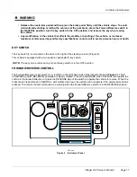
The hazard light switch (2) is located just below the turn signal switch

(Figure 10)

. To activate the hazard lights, make

sure that the turn signal switch is in the center (off) position, and pull the switch marked “hazard” until it is locked in
place by the turn signal switch. To deactivate the hazard lights, move the turn signal switch in either direction and
return it to the center position.

HORN

The horn button (3) is located on the end of the turn signal lever

(Figure 10)

. Press the button to activate the horn.

SPEEDOMETER

The speedometer (4) is located on the steering column

(Figure 10)

. The speedometer provides information on

vehicle speed, odometer, and trip odometer.

The Koso Speedometer has two buttons for selecting and/or adjusting the features and functions available. The
buttons are located on the lower front portion of the speedometer with the select button on the left, and the adjust
button on the right. The main screen for the speedometer shows the speed digitally (large 3 digit, seven segment
display, centrally located) with the bar graph around the periphery, and the odometer displayed below the speed (small
5 digit, seven segment display) denoted by ODO on the left side of the numbers.

The speedometer has three range settings: 160km/h, 260km/h, and 160MPH. The range setting may be indexed to the
next setting by pressing and holding the adjust button for 3 seconds from the main screen.

The speedometer also has a Trip A and Trip B meter function for recording user selectable distances. To access the
Trip A function, press the adjust button one time from main screen. The small 5 digit, seven segment display will now
indicate the distance travelled since the last Trip A reset and is denoted by TRIP A on the left side of the numbers. To
reset the Trip A meter, press the adjust button for 3 seconds from the Trip A function screen. To access the Trip B
function, press the adjust button one time from the Trip A screen. The small 5 digit, seven segment display will now
indicate the distance travelled since the last Trip B reset and is denoted by TRIP B on the left side of the numbers. To
reset the Trip B meter, press the adjust button for 3 seconds from the Trip B function screen. Pressing the adjust button
one time from the Trip B function screen will index the display to the fuel function screen. The fuel function screen is not
used on this application. Pressing the adjust button one time from the fuel function screen will return to the main screen.

The speedometer can display average speed, max speed, and riding time. To access the average speed screen, from
the main screen press the select button one time. The digital speed reading and the bar graph will indicate the average
speed since the last reset of the Trip B meter as denoted by AVE above the speed. Also on this screen, the 5 digit,
seven segment display will indicate riding time since the Trip B meter was last reset. When the riding time is displayed
as 00:00, the units are 00 hours and 00 minutes. When the riding time is displayed as 00-00, the units are 00 minutes
and 00 seconds. The average speed and riding time may be reset by pressing the select button for 3 seconds from the
average speed screen. NOTE: Resetting the average speed and riding time also resets the Trip B meter function.

To access the max speed screen, press the select button one time from the average speed screen. The maximum
speed achieved since the last reset will be displayed as denoted by MAX above the speed. To reset the max speed,
press the select button for 3 seconds from the max speed screen. To return to the main screen, press the select
button one time from the max speed screen.

To check the factory settings for proper speed indication for factory installed tires, simultaneously press the select and
adjust buttons for 3 seconds. The large 3 digit, seven segment display should indicated 20P while the small 5 digit,
seven segment display should indicate 0700-. The values may be adjusted by selecting the applicable digit (denoted
by flashing) using the select button and changing the value with the adjust button.

SEAT BELTS

LSV vehicles are equipped with seat belts, one for each occupant.

See following WARNING.

Page 22

Villager LSV Owner’s Manual

Summary of Contents for Villager LSV

Page 1: ...uild code range 0 0 0 0 0 0 0 0 0 0 0 0 0 0 0 0 CCI 102313101 VIN 5J5LD22Bx2Axxxxxx LOW SPEED VEHICLE THIS VEHICLE CONFORMS TO ALL APPLICABLE U S FEDERAL MOTOR VEHICLE SAFETY STANDARDS IN EFFECT ON TH...

Page 2: ......

Page 3: ...ormation contained in this document is subject to change without notice Club Car reserves the right to make design changes to vehicles without obligation to make these changes on units previously sold...

Page 4: ...u fast courteous service In the event your Club Car vehicle needs repairs or service please contact your local authorized Club Car dealer or distributor he will be able to provide technical advice per...

Page 5: ...ors 16 Seat Belts 22 Transporting Children 25 Pre Operation and Daily Safety Checklist 25 Driving Instructions 26 Transporting on a Trailer 28 Storage 29 Maintenance 30 Periodic Service Schedule 31 Pe...

Page 6: ...truck This results in a higher risk of injury or death in collisions even at low speeds The higher the speed of traffic around you the higher the risk of injury To reduce risks Do not operate this veh...

Page 7: ...cancer and birth defects or other reproductive harm REPORTING SAFETY DEFECTS If you believe that your vehicle has a defect which could cause a crash or could cause injury or death you should immediate...

Page 8: ...FETY DECAL AND FEATURE IDENTIFICATION The following pages contain safety decal and feature identification information For detailed information on specific features read the appropriate section in this...

Page 9: ...ng Instructions on wiper motor cover 3 101972001 Decal Do Not Ride in Bed Only with Cargo Bed Option 12 Tail Brake Turn Light 4 102322704 Decal VIN VILL 2 LSV 13 Slow Moving Vehicle Warning Triangle 5...

Page 10: ...5LD22Bx2Axxxxxx LOW SPEED VEHICLE THIS VEHICLE CONFORMS TO ALL APPLICABLE U S FEDERAL MOTOR VEHICLE SAFETY STANDARDS IN EFFECT ON THE DATE OF MANUFACTURE SHOWN ABOVE 7 6 9 xxxxxx xxxxxx xxxxxxxxxx xxx...

Page 11: ...6 3 1 4 6 3 2 a n d o th e r p a te n ts p e n d in g 5 2 1 1012647 Decal Patent 9 103757901 Decal Operating Instructions on wiper motor cover 2 101825101 Decal On Off 10 Tail Brake Turn Light 3 10232...

Page 12: ...THIS VEHICLE CONFORMS TO ALL APPLICABLE U S FEDERAL MOTOR VEHICLE SAFETY STANDARDS IN EFFECT ON THE DATE OF MANUFACTURE SHOWN ABOVE 9 8 7 10 xxxxxx xxxxxx xxxxxxxxxx xxxxxxxxxxxxxxxxx xxxxxxxxxxx xxxx...

Page 13: ...death WARNING A WARNING indicates an immediate hazard that could result in severe personal injury or death CAUTION A CAUTION with the safety alert symbol indicates a hazard or unsafe practice that co...

Page 14: ...place and are easy to read For vehicles with cargo beds remove all cargo before raising the bed or servicing the vehicle If the vehicle is equipped with a prop rod ensure that it is securely engaged...

Page 15: ...g the batteries wait 90 seconds for the controller capacitors to discharge 1 2 3 5 6 4 TOW RUN WARNING 1 2 3 Viewed from driver side of vehicle 1 Place TOW RUN Switch in TOW before disconnecting or co...

Page 16: ...he batteries but by people who use the batteries as well Please contact your nearest Club Car dealer or distributor for information on how to properly recycle your batteries 1403 Figure 2 Dispose of L...

Page 17: ...cle utilizes the IQ System 48 volt electric system Throughout this manual important features unique to each model are highlighted We urge the owner operator to read and understand this manual and to p...

Page 18: ...er s manual is valid for the build code range indicated on the back cover of this owner s manual PH0901 123456 BC54679 SERIAL NUMBER 4 1 2 3 1400 eps Figure 4 Serial Number Decal VEHICLE IDENTIFICATIO...

Page 19: ...column Figure 5 This vehicle is equipped with a two position pedal start key switch NOTE The key can be removed only when the key switch is in the OFF position FORWARD REVERSE CONTROL The Forward Rev...

Page 20: ...will alert the operator that the vehicle may be used but that it must be charged to completion as soon as possible The warning light will repeatedly illuminate for 10 seconds with 4 second intervals i...

Page 21: ...p on a gradual slope If the walk away braking function remains engaged for two seconds or more a warning buzzer will sound to alert the driver that motor braking has been activated WARNING Walk away b...

Page 22: ...TE The brake lights will illuminate when the park brake is engaged unless the key switch is in the OFF position TOW RUN SWITCH WARNING Place Tow Run switch in the TOW position before disconnecting or...

Page 23: ...hicle electrical system thus preventing vehicle electrical components from discharging the batteries 3 4 1 2 7A Figure 9 Tow Run Switch 1819 Figure 10 Turn Signal Lever Hazard Lights Horn and Speedome...

Page 24: ...tance travelled since the last Trip B reset and is denoted by TRIP B on the left side of the numbers To reset the Trip B meter press the adjust button for 3 seconds from the Trip B function screen Pre...

Page 25: ...To release the seat belt press the buckle release button 1 and allow the belt to retract Figure 11 If the belt does not retract smoothly pull it out and check for kinks or twists Then make sure it rem...

Page 26: ...passenger to hold a child in his or her lap while the vehicle is moving Be careful not to damage the seat belt webbing or hardware Inspect the seat belt system periodically Check for cuts fraying and...

Page 27: ...wear and damage If tires are worn or damaged replace then immediately Ensure replacement tires meet Federal Motor Vehicle Safety Standards FMVSS 109 and 119 requirements replacement tires must also ha...

Page 28: ...position When walk away braking is engaged the reverse buzzer should emit a distinct pattern of beeps See following WARNING WARNING Walk away braking will not limit vehicle speed to 1 mph 1 6 km h on...

Page 29: ...e reduce speed for adverse driving conditions such as wet surfaces or rough terrain Do not drive while under the influence of alcohol drugs or medications Use brakes to reduce speed when coasting down...

Page 30: ...slow down at the normal rate continue to press the brake pedal until the brakes dry out and normal performance returns CAUTION When stopped on a hill use the brake pedal to hold your position Do not...

Page 31: ...2 LSV 1069 lb 486 Kg Villager 2 2 LSV 1129 lb 512 kg NOTE A two car trailer should be rated at Villager 2 LSV 2 x 1069 lb 2138 lb 2 x 486 kg 972kg Villager 2 2 LSV 2 x 1129 lb 2258 lb 2 x 512 kg 1024...

Page 32: ...e Tow Run switch should be in Tow When in Tow mode the amber battery warning light will not illuminate Do not attempt to use the battery light as an indication of battery state while in storage 9 3 If...

Page 33: ...jewelry such as rings watches chains etc when servicing the vehicle Turn the key switch to OFF remove the key place the Forward Reverse switch in the NEUTRAL position and chock tires prior to servicin...

Page 34: ...on in the appropriate maintenance and service manual Lubricate brake slides per Lubrication Schedule See Wheel Brake Assemblies Section in the appropriate maintenance and service manual Brake system C...

Page 35: ...Brake Slides Dry Moly Lube CC P N 1012151 Semiannually by owner or trained technician or every 50 hours of operation whichever comes first Front suspension 2 fittings Chassis Lube EP NLGI Grade 2 Che...

Page 36: ...off all accessories before charging batteries NOTE Recycle or dispose of discarded batteries in accordance with local state and federal regulations Club Car electric vehicles use deep cycle batteries...

Page 37: ...the chart If using tap water Club Car s Service Parts Department offers two different deionzier systems one for vehicles equipped with the Single Point Water System SPWS CC P N AM1240701 and the othe...

Page 38: ...waste water properly 2 The electrolyte level in the batteries should be checked weekly Figure 14 Add distilled water only after charging unless the electrolyte level is below the top of the plates In...

Page 39: ...y Failure to do so may cause them to overheat during operation and could result in fire property damage or personal injury 3 After use charge the batteries The batteries should never be left discharge...

Page 40: ...d immediately Do not expose to rain or any liquid Keep the charger dry Do not use near fuels grain dust solvents thinners or other flammables Chargers can ignite flammable materials and vapors Connect...

Page 41: ...f an extension cord with the charger should be avoided If an extension cord must be used use a three conductor no 12 AWG American Wire Gauge or no 14 SWG British Standard Wire Gauge heavy duty cord wi...

Page 42: ...battery after it has been removed from the car CAUTION Water the batteries only AFTER charging Use only the water deionizer equipment CC P N AM1240701 to water batteries with the SPWS WATERING BATTER...

Page 43: ...from the water hose 5 Check the water quality light on the deionizer to make sure the light is green in color indicating acceptable water quality If the light indicates unacceptable water quality the...

Page 44: ...and call for service 3 When the red flow indicator balls stop moving immediately press the grey button to disconnect the regulator from the battery fill coupling 9 and squeeze the dust cover 10 to lig...

Page 45: ...vy soiling difficult stains or scratches blemishes or other body damage see the Maintenance and Service Manual NOTE Dispose of waste water properly ACCESSORIES There is a complete line of accessory eq...

Page 46: ...aluminum Rear body Armor Flex ArmorFlex Front body ABS Front body finish Automotive grade paint Tires Standard DOT rated 215 60 R8 Alloy Option DOT rated 205 50 R10 Radial DIMENSIONS WEIGHT Overall le...

Page 47: ...height 29 5 in 75 cm 29 5 in 75 cm BED BOX Overall Length 31 4 in 80 cm Width 37 9 in 96 cm Height 9 3 in 24 cm STANDARD SEATING CAPACITY 4 2 LIQUID CAPACITIES Transaxle 22 oz 0 67 liters 22 oz 0 67 l...

Page 48: ...NOT APPLY TO FAILURE DUE TO A Abuse or neglect such as overcharging undercharging improper battery fluid levels loose wiring or rusted or corroded hardware B Lack of proper maintenance as outlined in...

Page 49: ...WARRANTY OF ANY KIND EXPRESSED OR IMPLIED ANY IMPLIED WARRANTIES OF MERCHANTABILITY OR FITNESS FOR A PARTICULAR PURPOSE WHICH EXCEED THE OBLIGATIONS OR TIME LIMITS STATED IN THIS WARRANTY ARE HEREBY...

Page 50: ...UB CAR does not warrant that its battery is suitable for use in any application other than in its products As in the use of any battery a prudent owner will read and study the charger owner s manual t...

Page 51: ...LIMITED WARRANTY SHALL NOT APPLY TO FAILURE DUE TO 1 Abuse or neglect such as improper battery fluid levels loose wiring or rusted or corroded hardware 2 Lack of proper maintenance as outlined in the...

Page 52: ...t in material or workmanship or that occurs due to abuse or neglect including failure to provide reasonable and necessary maintenance accident or alteration is excluded from this limited warranty Some...

Page 53: ...Club Car R NOTES...

Page 54: ......

Page 55: ......

Page 56: ...Publication Part Number 103700406 Edition Code 1009D1010C 103700406 This manual is valid for vehicles with build codes between BC54699 and the one indicated at the top of this page...

Reviews: