background image


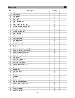
Parts List   


NO.    

Description 

Quantity 


Main frame 


Front  stabilizer 


Rear stabilizer 


Handlebar post  


Saddle post 


Saddle adjustable post 


Saddle 


Cap (for saddle adjustable post) 


Fastener (for saddle adjustable post) 


10 

Knob (for saddle adjustable post) 


11 

Knob (for handlebar post) 


12 

Fastener (for saddle post)  


13 

Saddle post knob   


14 

Sleeve (for handlebar) 


15 

Tension control cable 


16 

Front stabilizer cap 


17 

Rear stabilizer cap  


18 

Computer cable (upper) 


19 

Computer cable (lower) 


19 

Motor  


20 

Computer 


21 

Carriage bolt (for front & rear stabilizer) 


22 

Domed nut (for front & rear stabilizer) 


23 

Washer (for front & rear stabilizer ) 


24 

Hex.  Bolt (for handlebar post) 


25 

Washer (for handlebar post) 


26 

Pedal (R & L) 


27 

Central chain cover(R & L)  


28 

Chain cover (R & L)  


29 

Nut (for idle wheel fixture) 


30 

Plastic computer holder (R & L) 


31 

Handlebar 


32 

Foam grips (pair) 


33 

End caps (pair) 


34 

Hand pulse sensor 


35 

Screw (for chain cover) 


36 

Screw (for chain cover) 

14 


37 

Screw driver 


38 

Allen key wrench  


39 

Crank arm set  


40 

Protector (for handlebar post) 


41 

Screw (for handle pulse sensor ) 


42 

Hand pulse sensor wire 


43 

Sensor 


44 

Locknut (for saddle) 


45 

Washer (for saddle ) 


GB 

- 12 -  

Summary of Contents for PRO HM6004M

Page 1: ...GB PROGRAMMABLE MAGNETIC BIKE USER S MANUAL...

Page 2: ......

Page 3: ...the bike on an even non slippery surface Because of possible corrosion the usage of the home exercise bikes in moist areas is not recommended Check before the first training and every 1 2 months that...

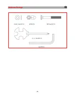
Page 4: ...Hardware Package GB 3...

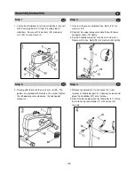
Page 5: ...ckwise the right pedal clockwise Step 3 1 Unscrew the pre assembled 4 hex Bolts 24 4 washers 25 2 Connect the upper computer cable 18 with lower computer cable 19 tightly 3 Put the handlebar post 4 in...

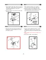
Page 6: ...e with 4 bolts 52 firmly Step 7 1 Attach saddle adjustable post 6 to saddle 7 secure with 3 x washer 45 and 3x locknut 44 2 Release the knob 10 from saddle post 5 Put saddle adjustable post 6 into sad...

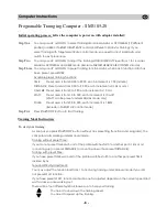
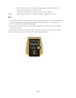
Page 7: ...t area is from 10 to 350 each increment is 10 watt WATT can be preset under MANUAL mode only PULSE Preset area is form 30 to 240 each increment is 1 BPM Exclude in TARGET H R control mode Step Five Pr...

Page 8: ...will STOP and ALARM for 6 beeps to remind you as the training protection You may select fixed preset target heart rate percentage or input your personal traning target heart rate figures Target Pulse...

Page 9: ...ring training Count Down The computer will count down from the preset Distance to 0 00 CALORIES Count Up The computer accumulates the calories comsuption from 0 to the max 990 cal during training Coun...

Page 10: ...o signal been transferred into the computer for 4 minutes the LCD display will shutt off automatically and all previous training datas will be stored You may press any button to have the computer rest...

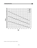
Page 11: ...e rate 168 x 0 7 117 pulse min During the first weeks it is advisable to start with a pulse rate of 101 afterwards increase it to 117 With increasing improvement of fitness the training intensity shou...

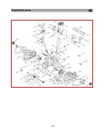
Page 12: ...Exploded drawing GB 11...

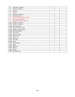
Page 13: ...lower 1 19 Motor 1 20 Computer 1 21 Carriage bolt for front rear stabilizer 4 22 Domed nut for front rear stabilizer 4 23 Washer for front rear stabilizer 5 24 Hex Bolt for handlebar post 4 25 Washer...

Page 14: ...post 2 A1001 Washer for flywheel 2 A1002 Washer for flywheel 2 A1003 Nut for flywheel 2 A1004 Bolt for idle wheel fixture 1 A1005 Bolt for idle wheel fixture 1 A1006 Nut for idle wheel 1 A1007 Steel...

Page 15: ...Training Pulse Rate The owner s manual is only for the customer reference GB 14...

Reviews: