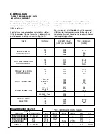
NOTE: IN THIS MANUAL, NOMINAL VOLTAGES ARE
USED WHEN REFERRING TO POWER SUPPLY
SYSTEMS. HOWEVER, WITH NO MODIFICA-
TION, THE XL HOIST WILL OPERATE ON A
RANGE OF VOLTAGES AS INDICATED BELOW:
NOMINAL
VOLTAGE
HERTZ
VOLTAGE
RANGE
230
208-240
60
460
440-480
60
220
200-240
50
380
365-395
50
415
400-430
50
575
550-575
60
WARNING
Failure to provide a proper power supply system for
the hoist may cause hoist damage and offers the
potential for a fire.
TO AVOID INJURY:
Provide the hoist with a 20 amp, minimum, overcurrent
protected power supply system per the National
Electrical Code (ANSI/NFPA 70) and applicable local
codes as instructed in this manual.
!
ELECTRICAL CONNECTIONS
SINGLE SPEED, DUAL VOLTAGE HOISTS (AND
MOTOR DRIVEN TROLLEYS)
Unless ordered on a special basis, single speed dual voltage
(230/460-3-60, 220/380-3-50 and 220/415-3-50) hoists are factory
wired to operate on 460-3-60 (or 380-3-50 or 415-3-50).
However, a conversion terminal board is provided to easily and
quickly change from 460 to 230 (or 380 to 220 or 415 to 220)
volt operation. The conversion terminal board is located adjacent
to the reversing contactor at motor end of hoist. If necessary,
change voltage connections before connecting hoist to power
supply system as follows:
1. Remove the motor cover (652-182). On units with
hook suspension, it will be necessary to remove the
counterweight (652-219) before removing motor
cover.
2. Shift all eight wires from row of terminals marked
“460” (or 380 or 415) to row of terminals marked
“230” (or 220).
CONVERSION TERMINAL BOARD
MOVE ALL 8 WIRES TO CONVERT FROM 460 TO 230
(380 TO 220, 415 TO 220) VOLT OPERATION
HOIST VOLTAGE
CONVERSION
3. Reassemble motor cover (and counterweight if so
equipped) to hoist frame.
4. Mark the tag attached to power cord to indicate
that the hoist has been converted to operate on 230
(or 220) volts and restamp hoist identification plate
accordingly.
If the hoist is suspended from a single speed motor driven trol-
ley, it will also be necessary to change the trolley motor
connections. To do this, remove the cover from the ter-
minal box mounted on the side of the trolley motor and
reconnect the trolley motor wires attached to the terminal
board as shown below:
ALL HOISTS
After making sure that the hoist (and motor driven trol-
ley) are wired to operate on the power supply system,
you are now ready to connect hoist power cord to the
power supply. Since these are three phase units, the
hoist motor can rotate in either direction depending on
how it is connected to the power supply. Therefore,
direction of hook movement must be checked during the
original installation and each time the hoist is moved to
a new location.
Always disconnect the hoist from the power supply system or
de-energize the power supply system and follow proper
Lockout/Tagout procedures when working (connecting
or disconnecting) with the hoist electrical connections.
Serious damage will result if the hook is run to upper or
lower limit of lift with hook moving in a direction oppo-
site to that indicated by the control station. Connect
hoist power cord to the power supply and check hook
movement as follows:
1. Move the manual disconnect switch handle to the
“OFF” position.
2. Connect the WHITE-PURPLE, RED AND BLACK wires
of hoist power cord to load side of disconnect switch.
Connect the GREEN wire of hoist power cord to
power supply ground.
TROLLEY VOLTAGE CONVERSION
(Connections shown are for 208-240 volt operation)
WARNING
FAILURE TO FOLLOW PROPER LOCKOUT/TAGOUT PROCEDURES
MAY PRESENT THE DANGER OF ELECTRICAL SHOCK.
TO AVOID INJURY:
DISCONNECT POWER AND LOCKOUT/TAGOUT DISCONNECT-
ING MEANS BEFORE REMOVING COVER OR SERVICING THIS
EQUIPMENT.
(2 TON ONLY)
9


