17
TROLLEY BRAKE (2 TON UNIT)
(Optional Accessory)
The stopping distance of the Motor Driven Trolley
equipped with an electric brake can be increased or
decreased by adjusting the brake pressure. To increase
brake pressure, and thereby decrease stopping distance,
move the brake spacer washers progressively from the nut
side of the brake field plate to the spring side. To
decrease the stopping distance, move the washers in an
opposite manner. Both studs must have the same number
of washers on the spring side of the brake field plate.
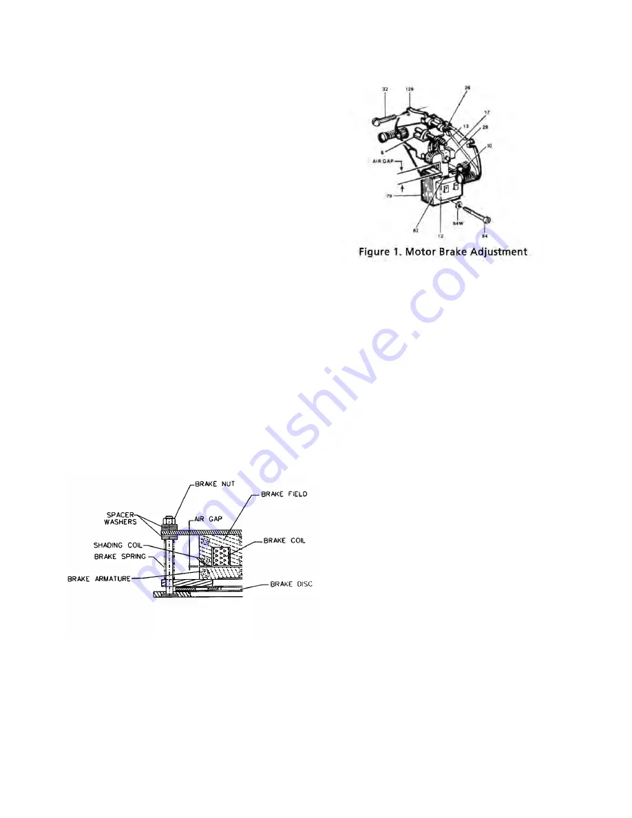
The correct air gap between armature and field, when
the brake is not energized, is 0.025 inch (.63 mm) and
need not be adjusted until the gap reaches 0.045 inch
(1.14 mm).
To adjust the air gap or brake pressure, proceed as follows:
1.
Disconnect hoist from power supply.
2.
Remove brake cover.
3.
Before adjusting air gap or brake pressure:
a.
Back off the brake nuts and examine friction lin-
ings and friction surfaces for excessive wear, scor-
ing or warpage.
b.
Check shading coils to be sure they are in place
and not broken. A missing or broken shading coil
will cause the brake to be noisy when trolley is
operated.
Any of these symptoms indicate the need for
replacement of parts.
4.
If brake pressure is to be adjusted, move brake spacer
washers to the desired side of the brake field plate to
increase or decrease pressure as indicated above.
5.
After spacer washers are positioned, turn brake nuts
clockwise gaging the air gap at both ends.
6.
Replace brake cover, reconnect the power and check
operation. If the stopping distance of the trolley is
not as desired, repeat the above.
TROLLEY BRAKE
ADJUSTMENT
TROLLEY BRAKE (3 THUR 7½ TON UNITS)
(Optional Accessory)
The brake can be ordered with the trolley or it is avail-
able in kit form for installation on a unit in the field. To
order a brake kit for an existing unit, order brake kit
Key No. 29 and indicate the serial number of the trolley
on which it is to be installed and the voltage on which
the trolley operates.
ADJUSTMENT
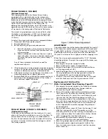
The motor brake should be checked periodically for wear of
the friction discs and/or proper adjustment of the solenoid
air gap. Refer to Figure 1. Normal lining wear will cause the
solenoid lever (8) to move away from the solenoid frame
(79) and thus increase the air gap and trolley stopping time.
When the air gap reaches approximately 11/16” the brake
should be adjusted. To adjust the air gap of the brake, pro-
ceed as follows:
1. De-energize the power supply to trolley.
2. Remove both access covers to expose brake.
3. Depress the plunger (13) towards the solenoid frame
until spring pressure is felt.
4. Hold the plunger firmly in the position and measure
the air gap between the mating (ground) surfaces of
the solenoid (79) and the solenoid plunger (29).
5. To adjust, turn both wear adjustment screws (10) equal
amounts clockwise until the air gap measures 13/32”.
Replacement of Friction Disc
(Refer to Exploded View Drawing, Page 47)
1. De-energize the power supply to the trolley and remove
the motor/brake assembly from the gear reducer.
Remove housing (3) from the brake.
2. Remove the entire support plate assembly by unscrew-
ing 3 screws (32). Remove the stationary disc (11) and
worn friction disc (12). Install the new friction disc, mak-
ing sure that the two stablizing springs are at 90° in
the recessed portion of the squared hole in the friction
disc, with the prongs pointing into the brake. Place the
stationary disc on the friction disc and re-assemble the
entire support plate assembly engages the guide pins
of the end plate.
3. Remove both access covers (5) from the housing (1) and
slide the housing with its shaft assembly on to the
mounting studs. Be sure the housing is assembled with
access windows above the horizontal centerline. Rotate
shaft to engage key into the hub keyway.
4. Re-assemble the motor/brake assembly to the gear
reducer using the four nuts and lockwashers.
5. Adjust air gap per above instructions (ADJUSTMENTS).
6. Re-energize power supply and operate trolley a few
times to make sure air gap is correct and then replace
access covers (5).


