18
RECOMMENDED SPARE PARTS
To insure continued service of the XL Hoist, the
following is a list of parts that are recommended
to be kept on hand at all times to replace parts
that have worn or failed. Parts applicable to your
unit should be stocked.
Key No.
Part Name
Qty. for Each
Hoist in Service
652-120
Limit Switch Assembly
1
652-130
Brake Coil
1
652-131
Brake Friction Disc
2
652-135
Transformer
1
627-563
Control Station Parts Kit
1
(2 Direction Station)
627-565
Control Station Switch Kit
1
(2 Direction Station)
635-155
Control Station Switch Kit
1
(4 Direction Station)
652-136
Hoist Reversing Contactor
1
652-137
Speed Selecting Contactor
1
(2 Speed Hoists Only)
652-138
Trolley Reversing Contactor
1
652-236
Trolley Speed Selector
1
(2 Speed Trolley Only)
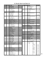
Refer to page 32 for ordering instructions and the
parts list for part numbers.
PREVENTIVE MAINTENANCE
In addition to the inspection procedure on page
12, a preventive maintenance program should be
established to prolong the useful life of the hoist
and maintain its reliability and continued safe use.
The program should include the periodic and fre-
quent inspections with particular attention being
paid to the lubrication of the various components
using the recommended lubricants (see page 15).
Replacement of Coil
(Refer to Figure 1 on page 17 and Exploded
View Drawing on page 48).
1. De-energize the power supply to the trolley and
remove the motor/brake assembly from the gear
reducer.
2. Remove housing (3) from the brake and disconnect the
coil wires from the cord.
3. Insert screw driver between support plate (126, Fig.1)
and the top of lever arm (17, Fig.1). Wedge these apart
and remove bearing pin (26, Fig.1) and solenoid lever
(8, Fig.1) with link (13, Fig.1) and plunger (29, Fig.1).
4. Remove plunger guide screw (84, Fig.1) and both
plunger guides (82, Fig.1). Slide old coil sideways out of
the frame (79, Fig.1). If coil is difficult to move, tap
lightly with a soft hammer.
5. Install new coil in the same relative position as the old
coil and replace the plunge guides (82, Fig.1) and screw
(84 and 84W, Fig.1).
6. Re-assemble follwing Step 3 in reverse order.
7. Re-connect the coil leads to the brake coil. Slide hous
ing and shaft assembly onto mounting studs, rotating
shaft to engage key into hub keyway. Be sure the
access covers are above the horizontal centerline.
8. Re-assemble motor/brake assembly to gear reducer
using the four nuts and lockwashers.
9. Adjust air gap per above instructions (ADJUSTMENT).
10. Re-energize power supply and operate trolley a few
times to make sure air gap is correct and then replace
access covers.


