background image

ENGLISH

8

TECHNICAL MANUAL

4. PREPARING  THE  MACHINE

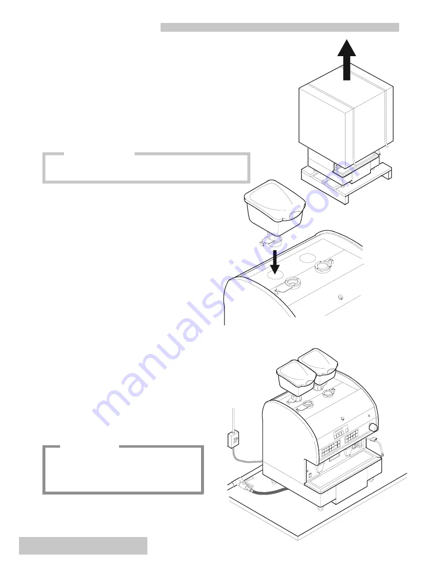
4.1 Unpacking

Proceed as follows to unpack the machine correctly:

1) Cut the straps around the packaging.
2) Pull the box off upwards.
3) Position the machine on the worktop.

4.3 Positioning the machine

There must be plenty of room for the appliance and for

using it correctly.

Prepare the place where the machine is to stand which

must be able to hold support its weight.

It is important that all the terminals of the connections to

the electricity mains and to the water mains are easy to reach

and in the immediate vicinity of the machine.

4.2 Preparing the grinder-dosers

Fit the coffee hoppers in place on the two grinder-dosers.

attention

For the machine to work properly it must stand on

a perfectly level surface.

Any corrections needed to level the machine can

be done by adjusting the feet.

We recommend keeping the packaging until the guarantee period

has expired.

information

All manuals and user guides at all-guides.com

Summary of Contents for AK

Page 1: ... 8720 7 2 0 5 QJOLVK 7 1 0 18 5 All manuals and user guides at all guides com a l l g u i d e s c o m ...

Page 2: ...All manuals and user guides at all guides com ...

Page 3: ...THIS MACHINE IS MADE IN COMPLIANCE WITH THE REQUIREMENTS OF THE FOLLOWING CEE DIRECTIVES 89 392 CEE 89 336 CEE 73 23 CEE All manuals and user guides at all guides com ...

Page 4: ... current safety standards Never exceed the capacity indicated on the adaptor or leads or the maximum power indicated on the adaptor l This appliance should only be used for what it has been designed for Any other use is considered improper and consequently dangerous The manufacturer cannot be held responsible for any damages caused due to an erroneous or irrational use The technician must remind t...

Page 5: ...chine SIGNALS and WARNINGS 25 7 4 Machine CYCLE counting 26 7 5 Configuration of the servicing warning 27 7 6 Button configuration 27 8 MACHINE COMPONENTS 28 8 1 Boiler 28 8 2 Heat exchanger 28 8 3 Automatic Water Inlet 28 8 4 Volumetric doser 28 8 5 Dispensing unit 29 8 6 Checking pressure 30 8 7 Anti flooding device 30 8 8 Valve unit 30 8 9 Pump system 31 8 10 Cappuccino maker 31 9 ELECTRONIC SY...

Page 6: ...or 5 Programming key 6 Steam dispensing knob 7 Steam dispensing spout 8 Hot water dispensing pipe 9 Pressure gauge 10 Grouts box 11 Coffee dispensing spout 12 Main switch for switching on machine 13 Feet 14 Functions control touch pad 15 Touch pad panel display 16 Cappuccino maker model AK model AKC All manuals and user guides at all guides com a l l g u i d e s c o m ...

Page 7: ...A 5 0 y t i c a p a c r e l i o B s e r t i l 7 g n i k r o w r e l i o B e r u s s e r p r a b 2 1 1 f o e r u s s e r P d e i l p p u s r e t a w r a b 5 0 f o e r u s s e r P e e f f o c d e s n e p s i d r a b 9 8 e v l a v y t e f a S n o i t a r b i l a c r a b 2 L h t d i W m c 7 5 P h t p e D m c 4 5 H t h g i e H m c 3 8 t h g i e W g k 4 9 3 DESCRIPTION OF THE INTERNAL COMPONENTS 1 Left ...

Page 8: ...ble to hold support its weight It is important that all the terminals of the connections to the electricity mains and to the water mains are easy to reach and in the immediate vicinity of the machine 4 2 Preparing the grinder dosers Fit the coffee hoppers in place on the two grinder dosers attention For the machine to work properly it must stand on a perfectly level surface Any corrections needed ...

Page 9: ...tion 1 connect the water mains 1 to the softener inlet 2 using the flexible pipe provided 2 rinse the softener resins checking that the water that is initially yellow becomes a clear colour 3 connect the softener outlet 3 to the machine 4 4 connect the machine drainage trough 5 to the drain 6 using the specific pipe provided taking care to avoid sharp bends or throttlings and keeping it slanted en...

Page 10: ...pump 5 3 Electrical connection l Connect the cable leading from the machine to the electricity mains l Install a circuit breaker 1 THREE PHASE 400V NEUTRAL EARTH C BL GV NE NE MA SINGLE PHASE 230V EARTH D NE BL GV NE MA THREE PHASE 230 EARTH BL GV NE NE MA 1 1 F C C F F LEGEND MA Brown Ne Black BL Blue GV Yellow Green C Machine cable F Electricity mains R S T Phase D Phase N Neutral Earth Effect t...

Page 11: ...Progr CLOCK PROGRAMM Press the MODE key Test input check PUSH BUTTONS and MICROSWITCHES test iNput Press the MODE key check of the INTERNAL COMPONENTS DIAGNOSTICS Press the MODE key EXIT the Programming function PLEASE SELECT t XXX YY YY YY PLEASE SELECT t XXX YY YY YY To exit programming turn the programming key counter clockwise Press the MODE key views WORK DONE optional INFO READING 6 1 Progra...

Page 12: ...ROGRAMM PI 1ESP GR1 n n preinfus PROGRAMM PI 1ESP GR1 n n preinfus PROGRAMM PI 2ESP GR1 n n PLEASE SELECT t XXX YY YY YY 6 2 Programming GRINDING 6 2 1 GRINDING TIME 6 2 2 PREINFUSION TIME Press ENTER to confirm and carry on programming the other selections Press the ENTER key Alter the preinfusion time by pressing the arrow keys nn is the preinfusion time sec for one cup of espresso coffee RECOMM...

Page 13: ...e C of the dispensing unit Press the ENTER key Change the temperature by pressing the arrow keys RECOMMENDED Minimum 80 C Maximum 90 C progRAMMING TEMP GR2 NN progRAMMING TEMP GR2 n n Press ENTER to confirm and carry on programming unit 2 PLEASE SELECT t XXX YY YY YY 6 2 3 TEMPERATURE of the DISPENSING UNITS 6 2 4 NUMBER of COFFEE GROUTS in the DRAWER Change the temperature by pressing the arrow k...

Page 14: ...s RECOMMENDED Maximum 100 progRAMMING COMPR OF DOUBLES NnN Press ENTER to confirm and carry on programming the other selections RECOMMENDED Maximum 100 progRAMMING compR OF DOUBLES NnN progRAMMING COMPR OF DOUBLES NnN PLEASE SELECT t XXX YY YY YY 6 2 5 COMPRESSION FORCE 6 3 Programming ADDED WATER optional Modify force by pressing the arrow keys Press the MODE key to enter ADDED WATER programming ...

Page 15: ...ess the MODE key Press the key of the dose wanted e g 1 ESPRESSO or MILK or TEA and wait for it to be dispensed PROGRAMMing 1 ESPRESSO PROGRAMMING 1 ESPRESSO Confirm the dose by pressing the DOSE key again and carry on programming the other doses PLEASE SELECT t XXX YY YY YY When programming the doses the selection LED flashes In the case of ADDED WATER function enabled you have to confirm the dos...

Page 16: ... confirm Press the arrow keys to change the DAY settings and confirm with ENTER Press the arrow keys to change the WEEKDAY settings and confirm with ENTER Press the arrow keys to change the HOUR settings and confirm with ENTER Press the arrow keys to change the MINUTES settings and confirm with ENTER Press the arrow keys to change the SECONDS settings and confirm with ENTER Press the MODE key to e...

Page 17: ...e micro test OK if the value on the display changes from 0 to 1 Press the ENTER key to go to the next check Disconnect the limit switch micro cable 3 and connect it to the central contact of the micro test OK if the value on the display changes from 0 to 1 Proceed in the same way to check dispensing unit 2 Press the ENTER key to go to the next check Press the ENTER key To check the grouts microswi...

Page 18: ...to go to the next check Press the ENTER key to go to the next check Functionality test of the dispensing unit 2 motor piston Press the ARROW keys to check correct motor operation Press the ENTER key to go to the next check TEST InPUT ch 1 0 TEST InPUT key 1 TEST InPUT CH 1 1 DIAGNOSTICS DIAGNOSTICS PSTN MTR GR1 TEST InPUT IN AUX 1 0 TEST InPUT IN AUX 2 0 TEST InPUT key 0 PLEASE SELECT t XXX YY YY ...

Page 19: ... are enabled Cappuccino maker steam suction solenoid valve Alarm buzzer if it exists Cappuccino maker air solenoid valve Cappuccino maker breather solenoid valve DIAGNOSTICS GRINDER GR 1 2 DIAGNOSTICS pUMP DIAGNOSTICS rEL gr 1 2 DIAGNOSTICS REL BLR DIAGNOSTICS rEL STEAM DIAGNOSTICS tEMP gr 1 2 DIAGNOSTICS rEL h2o DIAGNOSTICS AUX REL 1 2 DIAGNOSTICS AUX3 REL DIAGNOSTICS ev 1 DIAGNOSTICS REL ADD H2O...

Page 20: ... T or U in the cylinder Do not turn the key with the position OFF nn is the number of espresso coffees dispensed with the waiter key inserted To select the key wanted press ENTER repeatedly WAITER h 6 8 INFO READING optional 6 8 1 Viewing WAITER KEY data 6 8 2 Viewing data with the PERSON IN CHARGE KEY T and with the OWNER KEY U WAITER h 1 espR dEcAF GR1 To see how many decaffeinated coffees have ...

Page 21: ...il REV TO ZERO is shown on the display WAITER h REV TO ZERO Press MODE for at least 5 seconds until the display shows the script INFO READING Insert either key T or U in the cylinder Turn the key to the ON POSITION INFO READING To select the key wanted press ENTER repeatedly WAITER h To reset the data of all the keys keep the DOWNARROW pressed for at least 5 seconds TOTAL REV TO ZERO Press MODE to...

Page 22: ...el back 7 Switch the machine on and start it with the main switch and the ENTER key 8 Modify the machine s configuration parameters as explained in par 7 2 on the next page 9 Switch the machine off and after removing the front protection put the logic card switch back to the OFF position 7 1 PREPARING the MACHINE 10 Plug the electronic card in again put the protection and front body base back 11 S...

Page 23: ... time Milk Latte or Cappuccino were dispensed is modified xxare the hours yy are the minutes variation with 30 minute intervals By pressing the ARROWS buttons habilitate the machine for the requeit of the washing cycle Standard or American system 7 2 MACHINE CONFIGURATION yes no CONFIGURATION key n CONFIGURATION key y CONFIGURATION TOKENS N CONFIGURATION TOKENS y CONFIGURATION MILK WASH N CONFIGUR...

Page 24: ...FIGURATION GR 2 y By pressing the ARROWS buttons enables the brening of 2 automatic dispensings of a double long coffee optional By pressing the ARROWS buttons it enables loading of the machine configuration default values To confirm the entire configuration press simultaneously the buttons ENTER MODE CONFIGURATION double 2long GR2 N CONFIGURATION double 2long GR2 y To confirm press MODE To confir...

Page 25: ...R1 00 TOTal ALARMS sAFETY NN TOTal ALARMS TEMP gr 1 NN Press the ENTER key TOTal ALaRMS BOILER SENSOR NN NNN is the number of signals TOTal ALARMS VOL DOSER gr2 NN TOTal ALARMS PSTN MTR GR2 NN TOTal ALARMS NO COFFEE gr2 NN TOTal ALARMS compression gr2 NN TOTal ALARMS tEMP gr 2 NN Press the MODE key to exit 7 3 MACHINE SIGNALS and WARNINGS To visualize the other information press ENTER To revert to...

Page 26: ...lize the other information press ENTER To revert to zero press the ARROW DOWN button for at least 5 seconds To proceed with the configuration of the machine press MODE CYCLES DECAF TOTAL NNN cappuccinOS TOTAL NNN CYCLES COFFEE gr1 TOTAL NNN tEA TOTAL NNN MILK TOTAL NNN latte TOTAL NNN rev to zero CYCLES gr1 TOTAL 000 CYCLES COFFEE TOTAL nnn PLEASE SELECT t XXX YY YY YY CYCLES COFFEE gr1 TOTAL NNN ...

Page 27: ... buttons Standard or American press the ARROWS button CONFIGURAtion america bottons 7 6 BUTTON CONFIGURATION yes no CONFIGURAtion service At NN NNN CONFIGURAtION cycles 1 nn nnn CONFIGURAtION rev to NN NNN CONFIGURAtION cycles 2 nn nnn CONFIGURAtION america bottons PLEASE SELECT t XXX YY YY YY To confirm the entire configuration press simultaneously the buttons ENTER MODE attenzione Turn the machi...

Page 28: ...l a working level probe 3 l a minimum safety level probe 2 l an electronic level regulator in the electronic control unit l a hydraulic circuit with a solenoid valve 1 controlled by the control unit The level probes act as a pole in the low voltage electrical circuit when the level of the water drops the circuit interrupts itself and the electronic control unit sends an impulse to theAEA s solenoi...

Page 29: ...ters the operating conditions of the internal parts modifying the machine s original settings To avoid this happening there are some adjustment cams on the microswitches that ensure perfect operation all the time Carry out checks and maintenance periodically to keep the machine 100 efficient We recommend changing the following components after every 100 000 cycles 1 Coffee chute 2 Brush 3 O ring 4...

Page 30: ... the hydraulic circuit Antidepression valve The job of the antidepression valve is to avoid the recall of liquids through the steam spout while they are heating up It also eliminates the air inside the boiler when the machine is warming up 8 6 Checking pressure This is used to turn the heating elements on or off according to the pressure reached inside the boiler Regulation pressure can vary from ...

Page 31: ...r protection 6 Cappuccino maker 7 Air regulator adjusts milk froth 8 Milk frothing solenoid valve 8 10 Cappuccino maker 8 9 Pump system This component has the job of feeding the machine raising water pressure to 8 9 bar for dispensing coffee and filling up the boiler automatically 5 7 8 1 2 3 4 6 All manuals and user guides at all guides com a l l g u i d e s c o m ...

Page 32: ...R Hardware card 2 l DRIVER Hardware card 3 l CPU Software logic 4 l MOTHER BOARD Hardware card In addition the electronic system consists of l Push button panel and display l Actuator relays l LEDs l Microswitches l Level probes POWER CARD DRIVER CARD CPU CARD MOTHER BOARD CARD All manuals and user guides at all guides com ...

Page 33: ... coffee chute is clogged 0 Press the key 2 Enter grinding programming and reduce grinding time 3 Restore connection and or change the microswitch unit if necessary 1 Put coffee beans in the grinder doser hopper 2 Open the valve on the grinder doser hopper 3 Remove the coffee chute and remove fat residuals with hot water or change the coffee chute 4 The piston is locked in the high position either ...

Page 34: ...tch the machine off and then on 1 The motor transformer protection fuse has blown cHECK BOILER WATER LEVEL 2 Open all the cocks upstream from the machine 2 Softener cock closed 1 Check whether or not there is water in the mains 1 No water in the mains 3 Change the pump filter 3 Pump filter clogged 4 Change the solenoid valve filter 4 Loading solenoid valve filter clogged vol DOSER gr i or ii noT C...

Page 35: ...ature sensor PTC is either faulty or the connection is interrupted BOILER SENSOR NOT WORKING 2 Press the key 1 Restore connection and or change the temperature sensor if necessary 1 Unit temperature sensor PTC is either faulty or the connection is interrupted sensor gr i or ii 3 Press the key 2 Restore connection 2 Wiring interrupted cause remedy display 5 Restore connection and or change the load...

Page 36: ...TURE OF STEAMAND WATER IS COMING FROM THE STEAM SPOUT 1 Boiler water level is too high because the boiler level probe is wrongly positioned or there is limescale on it 1 Check the position of the level probe and change it if necessary WATER IS LEAKING FROM THE INTERNAL PUMP 1 Bottom gaskets deteriorated 2 Fitting and or pipe deteriorated 1 Change the bottom gaskets 2 Change the fitting and or pipe...

Page 37: ... or change the filter 2 Check the motor 3 Recalibrate the limiter valve 4 Change the pump 5 Check supply voltage or change the motor 1 The gauge is faulty 2 The pressure switch is incorrectly calibrated 3 The motor pump is incorrectly calibrated 1 Change the gauge 2 Recalibrate the pressure switch 3 Recalibrate the motor pump THE DISPLAY FAILS TO SIGNAL THERE IS NO COFFEE 1 The limit microswitch i...

Page 38: ...he seals THE MILK IS TOO HOT 1 The cappuccino maker s through hole is clogged 2 The diameter of the cappuccino injector hole is too big 1 Clean the hole with the re lative brush 2 Change the injector THERE ARE BUBBLES ON THE MILK FROTH 1 The air regulator is open too far 2 The air suction pipe is disconnected 1 Calibrate the air regulator correctly 2 Restore connection via the pipe WATER FOR TEAIS...

Page 39: ... 5SXPS RP QG 6XSSO MXPSHU FRLQ UHFRJQLVHU SDQVLRQ IRU FRLQ UHFRJQLVHU ODW SLQ SXVK EXWWRQ SDQHO DQG GLVSOD FRQQHFWLRQ 17 JUX QG 0LON SUREH 9DO 0 OLPLW VZLWFK 17 JUX 6DIHW SUREH 9DO 0FDVV JURXWV 17 JUX DQ 0 OLPLW VZLWFK 17 DX QG DQ 3 S 3 3 3 3 3 3 NH OLQH DLWHUV NH V RVH FRXQWHU U RVH FRXQWHU U 0 QIXVLRQ 17 JUX QG QG H V OLQHV FRP 0 UHVW 17 DX HYHO SUREH 17 OU QG NH OLQH 0 UHVW 17 DX QG QG NH OLQH ...

Page 40: ...r on high voltage side 7 Transformer on low voltage side 8 Fuse 11 2 High voltage electrical circuit 9 Connectors for unit cover safety microswitches 10 Frame earthing 11 Contactor 12 Main switch for starting the machine 13 24Vac motor supply 14 Power cable 15 Connection to the electricity mains See diagram on page 41 See connectors diagram on p 38 All manuals and user guides at all guides com ...

Page 41: ... 6 Unit heating element 7 Volumetric flowmeter 11 3 Low voltage electrical circuit 8 Unit connector 9 Boiler sensor 10 Normal level probe 11 Safety level probe minimum 12 Grouts drawer microswitch 13 Frame earthing See connectors diagram on page 38 All manuals and user guides at all guides com a l l g u i d e s c o m ...

Page 42: ...or 8 Right grinder motor 9 Boiler loading solenoid valve 10 Added water solenoid valve right unit 11 Tea mixing solenoid valve 12 Tea solenoid valve 13 Solenoid valve right unit 14 Pump motor 15 Frame earthing 16 Line contactor 17 Main switch 18 Pump motor capacitor 11 4 Electrical circuit of motors and solenoid valves See connectors diagram on page 38 See diagram on page 39 All manuals and user g...

Page 43: ...able 4 Programming keys unit 5 Push button panel display 6 P C for right push button panel 7 P C for cappuccino push button panel 8 Right push button panel cappuccino 9 Right push button panel 10 Left push button panel 11 Mother Board card 12 CPU card 13 DRIVER card 14 Power supply card 15 Connection to the right push button panel All manuals and user guides at all guides com ...

Page 44: ... Volumetric control gruppo 2 Motor unit 1 Motor unit 1 Motor unit 2 Motor unit 2 24V voltage Heating element unit 1 Heating element unit 2 Supply voltage 12V voltage 5V voltage Under normal working conditions the LEDs with asterisks must always be on COLOUR LEDS R V G Red Green Yellow 32 5 6833 5 9 9 9 32 5 5 38 5 200 1 6 1 1 87 216 6 92 7 6 7 5 9 7 5 027 027 027 027 027 027 027 027 5 6 7 0 0 0 0 ...

Page 45: ...wmeter 8 Injection tube right unit 9 Recirculation tube right unit 10 Left volumetric flowmeter 11 Injection tube left unit 12 Recirculation tube left unit 13 Gigleur Ø 0 8 unit 14 Filter 15 O ring unit cap 16 Unit cap 17 Boiler drain cock 18 Tea solenoid valve 19 Water outlet 20 Water inlet cock 21 Milk suction tube solenoid valve 22 Drainpipe 23 Water inlet pipe All manuals and user guides at al...

Page 46: ...raulic diagram 1 Check valve 2 Cappuccino maker 3 Coffee spout 4 Breather solenoid valve 5 Suction solenoid valve for cappuccino maker 6 Air solenoid valve 7 Air regulator 8 Distributor All manuals and user guides at all guides com a l l g u i d e s c o m ...

Page 47: ...ENGLISH 47 TECHNICAL MANUAL 12 3 Added water hydraulic diagram 1 Distributor 2 Added water solenoid valve 3 Unit solenoid valve 4 Coffee spout All manuals and user guides at all guides com ...

Page 48: ...All manuals and user guides at all guides com ...

Page 49: ...All manuals and user guides at all guides com ...

Page 50: ...C M A S p a Via dei Colli 66 31058 SUSEGANA TV ITALY Tel 0438 6615 Fax 0438 60657 INTERNET www cmaspa com E MAIL cma cmaspa com Cod 02000133 Rev 01 06 2001 All manuals and user guides at all guides com ...

Reviews: