ZL-GR6150-001-V1
Installation and Connection Instruction Manual
CMA (WUHU) Robotics Company Limited
10
to avoid cable twisting, winding, etc. At the same time, to avoid the interference of power line to encoder line, the
power line cable and encoder line cable are respectively placed in their own independent line slot. The connection
is shown in the figure below
:
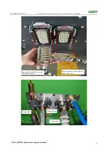
There are two aviation plug-in places on the right side of the robot control cabinet. The figure
below shows the physical diagram of power cable (including brake wire) and encoder cable aviation plug-in
terminal of robot control cabinet. The left side of the figure is an encoder cable connected with the driver in
the control cabinet; The right side of the aviation plug-in line is a power line (including the brake wire),
which is connected with the driver power port in the control cabinet. Both of the aviation plug-in wires will
be connected with the relevant interfaces under the robot body base.
Cable between disks
Teach pendant Explosion proof cabinet
Robot body
Air pipe
Control cabinet
Safety area
explosion hazard area


