ZL-GR6150-001-V1
Installation and Connection Instruction Manual
CMA (WUHU) Robotics Company Limited
12
3.5 Robot wrist end tool installation
Attention
When installing tools for the robot, it must be confirmed that the power supply of the robot
control cabinet and the main power supply have been cut off, and the installation must be
carried out according to the relevant installation requirements.
1
)
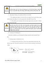
Dimension of flange surface for wrist end mounting
The flange of the mounting tool is at the end of the robot's wrist. The installation interface is shown in
the figure below, on the flange φ 104 threaded hole on the circumference, tighten the fastening screw. At
the same time, use the locating pin and the stop seam in the shaft to position the end tool.
Flange dimensions of end load mounting
2
)
Description of fixing screw
Please select the length of the fixed screw according to the depth of the screw hole of the mounting
flange to ensure the reliable threaded connection, as shown in the figure below. At the same time, tighten
the screw in the threaded hole according to the specified torque shown in the appendix "screw tightening
torque table".
Schematic diagram of end load mounting screw
Depth of screw hole
Mounting flange
Meshing length
Tool parts
Mounting screws
8-M5 depth 10
Uniform distribution

