background image

27

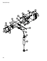
Item Part 

Description 

Qty. 

No. No.

  Electrical Panel and Timer

02103.93 

SCREW, TRUSS HEAD, 8-32 X 1/4"  

2

00411.00 

SWITCH, TIMER 

8

00501.00 

MOTOR, TIMER 

1

00408.60 

ASSEMBLY, TIMER (Includes Items 2, 3) 

1

00907.00 

SCREW, 6-32 X 1/2" 

6

02103.40 

RELAY, 15 AMP, 120VAC COIL 

2

00631.00 

RELAY, 120VAC, 2PDT 

1   

43030.00 

THERMOSTAT, WASH 

1

02103.15 

THERMOSTAT, B00STER 195°F 

1

10 

00416.00 

MOTOR, PERI-PUMP 115VAC 

2

11 

02106.07 

LABEL, WASH-RINSE TEMPERATURE 

1

12 

00907.50 

SCREW, 6-32 X 3/8" PAN HEAD PHIL. 

4

13 02106.08  BRACKET 

1

14 

00940.50 

SCREW, 10-32 X 3/8", TRUSS HEAD.  

2

15 

00415.00 

ASSY. PERI-PUMP (Includes Item 16 & 10) 

2

16 

02257.00 

TUBE, SQUEEZE 8" 

2


Summary of Contents for UC65e M2

Page 1: ...Avenue Garden Grove CA 92841 Toll Free 1 800 854 6417 Fax 1 714 895 2141 Issue Date 4 6 17 Manual P N 10310 00 rev A Printed in the USA For machines beginning with S N W160861096 and above Machine Serial No Model UC65e M2 CMA Dishmachines 12700 Knott Avenue Garden Grove CA 92841 Toll Free 1 800 854 6417 Fax 1 714 895 2141 0513903 B ...

Page 2: ...____________________ Tel ______________________ Parts Distributor _________________________________ Tel ______________________ ATTENTION The model no serial no voltage Hz and phase are needed to identify your machine and to answer questions The machine data plate is located on the lower front panel Please have this information ready if you call for service assistance National Service Department CM...

Page 3: ...arts lists 4 6 17 2 All Added GFI breaker to Item 2 Revision History The Revision History can contain part number changes new instructions or information that was not available at print time We reserve the right to make changes to these instructions without notice and without incurring any liability by making the changes Equipment owners may request a revised manual at no charge by calling CMA Dis...

Page 4: ...ii Model Description Model Description UC65e M2 High temperature hot water sanitizing dishwasher with built in 40 F 22 C rise booster heater 208 240VAC 60 1 ...

Page 5: ... Electrical Connections 2 Water Connections 4 Drain Connections 4 Initial Start up 6 Check List 6 Chemical Dispensing Pumps 7 Priming 9 Adjusting 10 Operation 11 Normal Wash Mode 11 Saf T Temp 12 Cleaning and Maintenance 13 Cleaning 13 Deliming 15 Maintenance 16 Troubleshooting 17 Service Replacement Parts 19 Electrical Schematic 50 Timing Chart 51 ...

Page 6: ...iv Blank Page This Page Intentionally Left Blank ...

Page 7: ...rcial Cooking Operations NFPA 96 CAUTION Be careful when lifting and moving the dishwasher to prevent damage to the machine NOTE The installation of the dishwasher must comply with local health codes 5 Compare the installation site utility connections with the dishwasher utility connections and make sure that they are the same 6 The dishwasher can be installed as a free standing unit or under a bu...

Page 8: ...in breaker or service disconnect switch then lock out and tag it to indicate that work is being performed on the circuit CAUTION Permanent damage to the dishwasher may occur if it is improperly connected to the main electrical supply Never install a power cord and plug to the dishwasher or connect the dishwasher to a standard or GFI electrical outlet or GFI electrical breaker The dishwasher must b...

Page 9: ... 2 L1 L2 N L1 L2 NEUTRAL 208 240V 115V 115V G 3 208 240V 60Hz 1 THREE POWER WIRES WHICH INCLUDES A CURRENT CARRYING NEUTRAL AN ADDITIIONAL WIRE MUST BE PROVIDED FOR MACHINE GROUND CONNECT THE INCOMING POWER AS SHOWN AT LEFT REMOVE THE LEFT SCREW ON THE FRONT LIP OF THE TERMINAL BOX LIFT AND REMOVE THE COVER TO ACCESS THE TERMINAL BLOCK A B THREAD THE POWER CABLE THROUGH THE MIDDLE SLOT IN THE DISH...

Page 10: ...water supply and drain hoses are not kinked 1 The dishwasher has a 6ft 3 4 I D drain hose The maximum drain height connection must not exceed 3 ft 9 m The recommended drain height is 17 4 m or less above the floor 2 The drain hose is secured to the rear of the machine by a clamp to maintain a goose neck bend in the drain hose 3 A 3 4 hose barb fitting is strapped to the drain hose to use in connec...

Page 11: ...e connected to a WYE FITTING DO NOT REPOSITION THE DRAIN HOSE DO NOT ADD AN EXTENSION TO THE DRAIN HOSE 0 60 10 20 40 30 50 psi 3 4 MNPT HOSE ADAPTER DRAIN HOSE DRAIN MUST BE VENTED TO PREVENT SYPHONING 1 1 2 WYE FITTING 18 OPTIMUM 3FT MAX Drain Connections ...

Page 12: ...mical pick up tubes are installed in the proper containers 6 Make sure that the sump filter is in place 7 Make sure that the overflow tube is installed and firmly seated in the sump 8 Make sure that the spray arms are in place and that they spin freely 9 Fully close the dishwasher door 10 Turn hot water supply on and check for leaks in the main water supply piping connected to the dishwasher Insta...

Page 13: ... the illustration on the next page 7 The detergent supply should be a non chlorinated liquid detergent 8 The rinse aid enters the final rinse piping through a fitting located on the upper left rear side of the dishwasher The fitting is located near the vacuum breaker The chemical supplier will choose the appropriate liquid rinse aid Initial Start up ATTENTION Contact a local chemical supplier for ...

Page 14: ...dishwasher near the vacuum breaker Detergent Injection Point Rinse aid Injection Point The illustrations below show the location of the detergent and the rinse aid injection points Chemical Injection Points 9 Your chemical supplier should adjust the dispensers for the supplied product 10 Place the chemical supply containers as close to the dishwasher as possible 11 Do not elevate the chemical cont...

Page 15: ...on DOWN to the R A rinse aid position for thirty seconds Release the push button 5 Close the door Initial Start up START DRAIN EXT WASH ON OFF POWER OFF ON PRIME DET R A 0 I Chemical Dispenser Prime Switch The chemical dispensing pumps must be primed during initial start up and whenever a chemical container A momemtary two position PRIME switch is located on the front control panel to do this The ...

Page 16: ...of rinse aid that is dispensed Turn the right half clockwise to increase the amount of rinse aid dispensed RINSE AID PUMP EXTEND WASH SAFE T TEMP DET PUMP RINSE VALVE DRAIN PUMP WASH PUMP HOMING CAM D E T E R G E N T R I N S E A I D CCW CW Adjusting the Chemical Dispenser Pumps The amount of detergent and rinse aid that are dispensed during the dishwasher cycle are controlled by adjustable cams on...

Page 17: ...ish rack Place plates glasses cups and bowls in a peg rack Place utensils in a single layer in a flat bottom rack Place pots and pans in a flat bottom rack Do not overload the dish racks 10 Slide 1 dish rack into the wash compartment making sure that wares do not interfere with the rotating spray arms Do not wash more than 1 dish rack at a time 11 Close the front door fully then press and hold the...

Page 18: ...low 1 The Safe T Temp constantly monitors the water temperature inside final rinse booster 2 If the temperature inside the booster heater falls below 180ºF 82ºC then the Safe T Temp will extend the wash cycle time until the booster heater water temperature reaches the proper temperature 3 The in cycle light will remain illuminated during the Safe T Temp Mode 4 The RINSE water temperature gauge mus...

Page 19: ...lly to keep the soil or waste particles from falling into the sump 7 Clean the sump filter by rinsing with clean water Be sure to back flush the filter Do not strike the filter against solid objects 8 Check the sump for foreign material and clean as required 9 Replace sump flter and the overflow tube 10 Make sure that spray arms turn freely 11 Check the chemical containers and refill as required 1...

Page 20: ...an water 6 Re install the rinse arm end plugs if they were removed 7 Remove the wash spray arms and flush with clean water 8 DO NOT USE STEEL WOOL TO CLEAN THE INTERIOR OF THE MACHINE 9 Contact the chemical supplier for Deliming if required see next page 10 Wipe the interior and exterior of the machine with a soft cloth and a mild detergent DO NOT HOSE THE EXTERIOR OF THE MACHINE WITH WATER 11 Rea...

Page 21: ...or serious injury may result when Deliming solution is mixed with sodium hypochlorite chlorine bleach sanitizing agent Mixing may cause hazardous gases to form Deliming solution and other acids must never be mixed with chlorine iodine bromine or fluorine CAUTION Skin contact with Deliming solutions can cause severe irritation and possible chemical burns Always wear protective clothing and googles ...

Page 22: ...n accumulated lime deposits from the wash tank heating element 7 Inspect the scrap screen and replace it if damaged 8 Check the spray arms and replace or repair if damaged 9 Clean the chemical dispenser pick up tubing for the detergent and rinse aid pumps Follow the maintenance schedules below to keep the dishwasher operating most efficiently To clean the pick up tubing 1 Remove the pick up tubes ...

Page 23: ...shwasher ON Open supply valve Adjust the PRV setting Clean strainer Contact Service Agent Refill chemical container Clean replace tube Replace tubing Straighten tubing Dishwasher stays in wash cycle Safe T Temp extends wash mode to allow final rinse water booster temperature to reach 180 F 82 C Contact Service Agent because booster thermostat is defective Poor wash results Wares incorrectly loaded...

Page 24: ...18 Blank Page This Page Intentionally Left Blank ...

Page 25: ...ster 22 Power Box Wiring 24 Electrical Panel and Timer 26 Control Panel 28 Upper Final Rinse Piping 30 Wash and Rinse Spray Arms 32 Drain Pump and Hoses 34 Wash Tank Heater and Drain 36 Fill Solenoid Valve 38 Detergent Pump 40 Rinse aid Pump 42 Panels 44 Door 46 Dish racks Line Strainer and PRV 48 ...

Page 26: ...20 Wash Pump Motor 1 2 6 3 4 5 7 9 8 10 11 12 13 ...

Page 27: ...left hand threads 1 4 02103 04 WASHER LOCK 1 4 1 5 02103 05 WASHER PLAIN M6 1 6 02103 06 IMPELLER 1 7 02103 07 SEAL 1 8 02103 30 GASKET PUMP 1 9 02103 09 BACKPLATE PUMP 1 10 02103 08 NUT M4 9 11 02103 10 PUMP MOTOR ASSEMBLY COMPLETE 220VAC 60 1 1 12 02103 37 COVER REAR MOTOR FAN 1 13 02103 11 CAPACITOR 16μF 1 Wash Pump Motor ...

Page 28: ...22 Booster 10 12 11 10 13 13 15 9 9 10 9 6 5 9 3 1 7 8 4 14 2 ...

Page 29: ... X 1 2 HOSE 1 6 02103 23 TEE RINSE THERMOMETER 1 7 02103 19 THERMOSTAT HI LIMIT FIXED SNAP 240 F 1 8 02106 01 TANK BOOSTER WELDMENT 1 9 02103 21 CLAMP GEAR TYPE 7 16 SST 3 10 02103 22 HOSE 1 2 ID A R 11 02103 24 FITTING BOOSTER THERMOMETER 1 12 02103 25 THERMOMETER 2 DIAL 7 CAPILLARY 1 13 03232 00 PLUG 1 8 2 14 00965 00 NUT 6 32 W NYLON INSERT 2 15 02103 28 FITTING BOOSTER THERMOSTAT 1 When the 6k...

Page 30: ...24 Power Wiring Box 4 12 9 11 3 8 7 6 5 13 1 8 2 10 ...

Page 31: ... 51 SCREW 6 32 X 1 4 2 5 13426 50 LUG GROUND 1 6 00905 82 SCREW 1 4 20 X 3 8 1 7 02106 05 BLOCK TERMINAL 4 POLE 1 8 00940 50 SCREW 10 32 X 3 8 TRUSS HEAD 2 9 02106 15 BUSHING STRAIN RELIEF SMALL A R 10 02103 48 CONTACTOR 3 POLE 25 40A 120VAC COIL 1 11 00940 00 SCREW 10 32 X 1 4 2 12 02106 06 RELAY DPDT 30A 120VAC COIL 1 13 06202 46 LABEL GROUND 1 ...

Page 32: ...26 Electrical Panel and Timer 1 6 6 7 8 9 11 12 13 14 15 16 10 5 3 2 4 ...

Page 33: ...W 6 32 X 1 2 6 6 02103 40 RELAY 15 AMP 120VAC COIL 2 7 00631 00 RELAY 120VAC 2PDT 1 8 43030 00 THERMOSTAT WASH 1 9 02103 15 THERMOSTAT B00STER 195 F 1 10 00416 00 MOTOR PERI PUMP 115VAC 2 11 02106 07 LABEL WASH RINSE TEMPERATURE 1 12 00907 50 SCREW 6 32 X 3 8 PAN HEAD PHIL 4 13 02106 08 BRACKET 1 14 00940 50 SCREW 10 32 X 3 8 TRUSS HEAD 2 15 00415 00 ASSY PERI PUMP Includes Item 16 10 2 16 02257 0...

Page 34: ...28 Control Panel 1 4 5 6 7 8 9 10 11 11 12 12 8 11 11 2 2 3 ...

Page 35: ... LABEL FACIA UC65e M2 1 4 15523 10 SWITCH ROCKER START MOMENTARY 1 5 15524 00 SWITCH ROCKER MAINTAINED 1 6 15523 50 SWITCH ROCKER DRAIN FILL 1 7 00911 10 SCREW TRUSS SLOT 8 32 X 3 8 2 8 02103 57 SWITCH MOMENTARY PRIME 1 9 02103 50 SWITCH ON OFF 1 10 02106 10 PANEL FACIA UC65e M2 1 11 04086 00 10 WASHER 4 12 03801 00 10 32 LOCK NUT 2 ...

Page 36: ...30 Upper Final Rinse Piping 10 13 8 7 6 2 1 1 4 5 4 2 2 12 14 15 1 9 11 3 ...

Page 37: ...K 1 5 02103 64 MANIFOLD RINSE 1 6 02103 65 INJECTOR FITTING 1 7 00425 54 TUBING 1 4 NATURAL A R 8 00923 50 NUT KEP 1 4 20 2 9 02103 04 WASHER SPLIT LOCK 1 4i 304SS 2 10 02103 69 BRACKET VACUUM BREAKER 1 11 00721 00 NUT JAMB 1 2 1 12 02103 71 VACUUM BREAKER 1 2 BRASS 1 13 02103 72 REPAIR KIT VACUUM BREAKER 1 2 1 14 40014 00 COUPLER 1 2 MPT X 1 2 HOSE 1 Upper Final Rinse Piping ...

Page 38: ...32 Wash and Rinse Spray Arms 13 14 1 2 3 4 5 6 7 21 21 20 19 21 22 19 18 23 20 21 8 11 10 15 12 12 16 9 17 18 23 6 8 9 ...

Page 39: ...MBLY Includes Item 8 2 13 02103 88 WASHER NYLITE 4 14 02103 89 BOLT 1 4 20 X 1 4 15 02103 90 SHAFT LOWER 1 16 02103 91 O RING 1 17 02103 92 HUB RINSE ARM MOLDED 2 18 02103 93 SCREW TRUSS HEAD 8 32 X 1 4 4 19 02103 94 ARM RIGHT HAND RINSE 7 JETS 2 20 02103 95 ARM LEFT HAND RINSE 8 JETS 2 21 02103 96 CAP RINSE ARM 5 16 24 4 22 02103 97 SPINDLE RINSE ARM 2 23 02103 98 SPACER NUT 2 02103 99 RINSE ARM ...

Page 40: ...34 Drain Pump and Hoses 16 5 4 4 15 To upper washarm hub From Final Rinse Manifold 4 3 1 2 11 10 5 5 7 8 5 24 24 23 18 19 20 21 22 2 6 12 11 2 14 13 17 9 TO BOOSTER INLET ...

Page 41: ...MP HOSE GEAR TYPE 1 13 16 2 3 4 MAX 2 12 02104 11 HOSE SUCTION WASH PUMP 1 13 50109 00 CLAMP HOSE 28 2 14 02104 13 HOSE DISCHARGE WASH PUMP 1 15 02103 81 HOSE UPPER WASH ARM 1 16 03107 50 HOSE RUBBER 1 2 ID X 84 OD A R 17 02103 68 COUPLER 3 4 MPT X 3 4 HOSE BARB 1 18 02106 19 HOSE DRAIN MOLDED 1 19 02106 21 NUT ANTI SIPHON VALVE 1 20 02106 23 O RING 1 21 02106 25 BALL 3 8 DIAMETER STAINLESS STEEL ...

Page 42: ...36 Wash Tank Heater and Drain 3 20 27 26 25 4 3 4 18 17 16 15 14 13 8 7 6 5 1 2 10 2 9 13 12 5 3 4 11 19 23 24 21 22 32 33 32 33 34 35 29 28 30 31 36 37 ...

Page 43: ...40 X 5 8 PAN HEAD 2 15 43019 00 SWITCH DOOR 15 AMP 1 16 02104 32 BRACKET SWITCH 1 17 02104 33 PLATE SWITCH NUT 1 18 02104 34 ELBOW PUMP SUCTION 1 19 02104 35 GASKET PUMP SUCTION 1 20 02104 36 FLANGE PUMP SUCTION 1 21 02104 37 HOSE 1 4 ID X 3 8 OD A R 22 02104 38 ELBOW 3 8 TUBE X 1 4 NPT 1 23 02104 39 GASKET 1 4 FIBER 1 24 02104 40 LOCKNUT 1 4 PLASTIC 1 25 02104 41 FILTER SUMP 1 26 02100 57 FILTER ...

Page 44: ...38 Fill Solenoid Valve 7 8 6 2 3 4 1 5 9 10 ...

Page 45: ...D COIL J E 1 3 03603 20 1 2 WATER SOLENOID BONNET 1 4 00786 00 WATER SOLENOID VALVE PLUNGER 1 5 00707 00 1 2 WATER SOLENOID REPAIR KIT 1 6 40013 00 FITTING BARB HOSE 1 7 02106 11 BRACKET VALVE UC65E 1 8 02103 16 BOLT HEX FLANGE 1 4 20 X 3 8 2 9 03604 50 FITTING FLOW DISC DEMA 1 10 03604 10 WASHER FLOW 1 Fill Solenoid Valve ...

Page 46: ...40 Detergent Pump 7 8 9 6 4 14 1 2 3 5 5 10 10a 11 12 13 13 9d 9c 9b 9a ...

Page 47: ... NYLON 4 4 6 02257 00 TUBE SQUEEZE 8 1 7 00911 00 SCREW 8 32 X 1 2 PANHEAD 4 8 00418 00 COVER PUMP 1 9 00419 00 ASSEMBLY ROLLER 1 10 00919 00 SCREW 10 32 X 1 1 2 PANHEAD 2 10a 00918 10 SCREW 10 32 X 1 1 2 FLATHEAD 1 11 00417 10 BLOCK PUMP 1 12 00416 00 MOTOR PUMP 115VAC 1 13 00448 00 CONNECTOR MALE BARREL 2 14 02104 52 ELBOW 1 4 HOSE BARB 1 00415 00 ASSEMBLY PERI PUMP COMPLETE 1 Includes Items 6 1...

Page 48: ...42 Rinse Aid Pump 7 8 9 6 10 10a 11 12 13 13 4 2 3 5 1 14 15 16 ...

Page 49: ...0 TUBE SQUEEZE 8 1 7 00911 00 SCREW 8 32 X 1 2 PANHEAD 4 8 00418 00 COVER PUMP 1 9 00419 00 ASSEMBLY ROLLER 1 10 00919 00 SCREW 10 32 X 1 1 2 PANHEAD 2 10a 00918 10 SCREW 10 32 X 1 1 2 FLATHEAD 1 11 00417 10 BLOCK PUMP 1 12 00416 00 MOTOR PUMP 115VAC 1 13 00448 00 CONNECTOR MALE BARREL 2 14 00425 54 TUBING CHEMICAL 1 4 NATURAL A R 15 02106 12 CONNECTOR 5 32 X 1 8 1 00415 00 ASSEMBLY PERI PUMP COMP...

Page 50: ...44 Panels 12 11 9 9 9 7 8 7 6 5 1 4 2 3 10 14 14 13 12 14 ...

Page 51: ...2 LABEL GAUGE 1 5 02104 63 GAUGE PRESSURE 0 60PSI 1 6 02103 25 THERMOMETER 2 DIAL 7 CAPILLARY 2 7 00929 00 BOLT 1 4 20 X 3 4 TRUSS HEAD 2 8 02104 66 PANEL FRONT UC65e 1 9 02104 67 FOOT ADJUSTING 4 10 02104 68 NUT KEPS 10 32 1 11 02104 69 WRAP OUTER PANEL 1 12 02104 70 CLAMP DOUBLE CONDUIT 3 13 02106 13 PANEL REAR 1 14 02103 39 SCREW TRUSS HEAD 10 32 X 3 8 4 15 02104 85 FRAME STAND 1 ...

Page 52: ...46 Door 1 5 4 3 2 3 2 6 7 ...

Page 53: ...o No Door 1 02104 73 DOOR WELDED ASSY 1 2 02104 76 ARM DOOR SPRING 2 3 02104 77 SPRING DOOR 2 4 02104 78 ACTUATOR DOOR SWITCH 1 5 00911 10 SCREW 8 32 X 3 8 TRUSS HEAD 2 6 02104 88 SEAL DOOR HINGE RH 1 7 02104 87 SEAL DOOR HINGE LH 1 ...

Page 54: ...48 Dish Racks Line Strainer PRV 1 2 3 4 ...

Page 55: ...49 Item Part Description Qty No No Dish Racks Line Strainer PRV 1 12960 01 DISH RACK BOWL A R 2 12960 03 DISH RACK PEG A R 3 03602 50 STRAINER LINE 1 2 Y 1 4 13602 20 VALVE PRESSURE REGULATING PRV 1 ...

Page 56: ...50 Electrical Schematic ...

Page 57: ... RINSE AID PUMP 3 DRAIN PUMP 4 RINSE VALVE 70 TIME SEC 0 40 20 10 30 50 60 80 90 120 110 100 1 HOMING CAM 2 WASH PUMP 7 EXTENDED WASH 8 SAFE T TEMP 6 CMA Dishmachines DRAWING NO TIMING CHART 05CTIME UC65e Timing Chart ...

Page 58: ...52 Blank Page This Page Intentionally Left Blank ...

Reviews: