2
Installation
Electrical Connections
GFI
0
60
10
20
40
30
50
psi
0
60
10
20
40
30
50
psi
0
60
10
20
40
30
50
psi
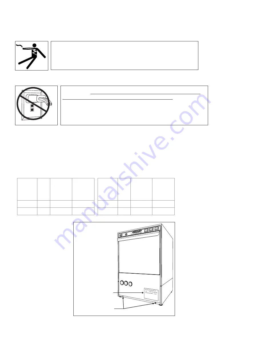
DATA PLATE
FRONT PANEL
SCREW LOCATION
1. Check the electrical specifications on the machine data plate then remove the lower
front panel to access the power input terminal block on the base of the machine.
2. Do not use a power cord and plug or connect to a standard or Ground Fault Interrupter
(GFI), electrical outlet or a Ground Fault Interrupter (GFI) breaker. The dishwasher must
be hard-wired to a junction box or service disconnect switch.
WARNING:
Electrocution may occur when working on ener-
gized circuits. Disconnect power at the main breaker or service
disconnect switch, then lock out and tag it to indicate that work
is being performed on the circuit.
CAUTION:
Permanent damage to the dishwasher may occur if it
is improperly connected to the main electrical supply. Never install
a power cord and plug to the dishwasher or connect the dishwasher
to a standard or GFI electrical outlet or GFI electrical breaker. The
dishwasher must be hard
-
wired to a dedicated appropriately sized
circuit breaker or service disconnect switch.
Elec. Specs
Rated
Amps
Minimum
Supply
Circuit
Ampacity
Maximum
Overcurrent
Overcurrent
Protective
Device
208/60/1
29
40
40
240/60/1
31
40
40
Elec. Specs
Rated
Amps
Minimum
Supply
Circuit
Ampacity
Maximum
(Breaker Size)
(Breaker Size)
Protective
Device
208/60/1
22
30
30
240/60/1
24
30
30
40˚F/22˚C Rise Electric Booster (4kW)
70˚F/39˚C Rise Electric Booster (6kW)
Summary of Contents for UC65e M2
Page 6: ...iv Blank Page This Page Intentionally Left Blank ...
Page 24: ...18 Blank Page This Page Intentionally Left Blank ...
Page 26: ...20 Wash Pump Motor 1 2 6 3 4 5 7 9 8 10 11 12 13 ...
Page 28: ...22 Booster 10 12 11 10 13 13 15 9 9 10 9 6 5 9 3 1 7 8 4 14 2 ...
Page 30: ...24 Power Wiring Box 4 12 9 11 3 8 7 6 5 13 1 8 2 10 ...
Page 32: ...26 Electrical Panel and Timer 1 6 6 7 8 9 11 12 13 14 15 16 10 5 3 2 4 ...
Page 34: ...28 Control Panel 1 4 5 6 7 8 9 10 11 11 12 12 8 11 11 2 2 3 ...
Page 36: ...30 Upper Final Rinse Piping 10 13 8 7 6 2 1 1 4 5 4 2 2 12 14 15 1 9 11 3 ...
Page 44: ...38 Fill Solenoid Valve 7 8 6 2 3 4 1 5 9 10 ...
Page 46: ...40 Detergent Pump 7 8 9 6 4 14 1 2 3 5 5 10 10a 11 12 13 13 9d 9c 9b 9a ...
Page 48: ...42 Rinse Aid Pump 7 8 9 6 10 10a 11 12 13 13 4 2 3 5 1 14 15 16 ...
Page 50: ...44 Panels 12 11 9 9 9 7 8 7 6 5 1 4 2 3 10 14 14 13 12 14 ...
Page 52: ...46 Door 1 5 4 3 2 3 2 6 7 ...
Page 54: ...48 Dish Racks Line Strainer PRV 1 2 3 4 ...
Page 56: ...50 Electrical Schematic ...
Page 58: ...52 Blank Page This Page Intentionally Left Blank ...


