


ii
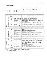
Max. Continuous
Baking Time
5 seconds
5 seconds
15 seconds
Controlled by Braking Unit
5
Max. Duty
3 % ED
2 % ED
5 % ED
5 % ED
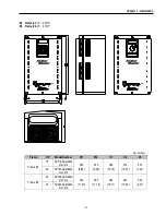
Weight
[lbs]
10.4 10.4 10.6 10.8 17.0 17.0 30.6 31.7 44.1 44.1
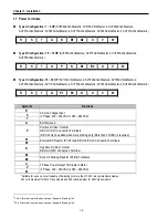
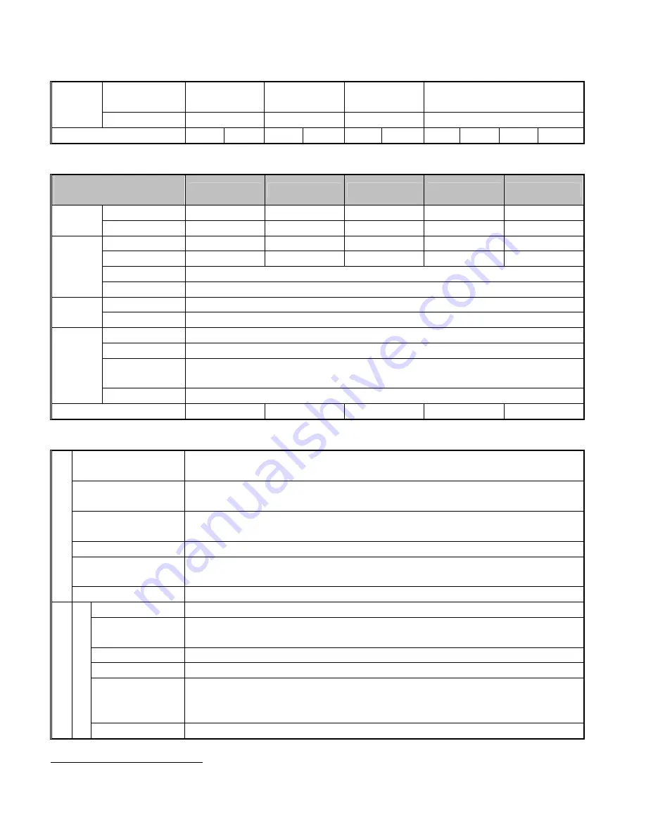
460V Class (40 ~ 100HP)
Model Number
SV xxx ACtionMaster - 4
300
370
450
550
750
HP
40 50 60 75 100
Motor
Rating
1
kW
30 37 45 55 75
Capacity
2
[kVA]
45 56 68 82 100
FLA [A]
61 75 91 110 152
Frequency
0 ~ 400 Hz (0-120Hz for Vector control)
Output
Ratings
Voltage
380 ~ 460 V
3
Voltage
3 Phase, 380 ~ 460 V (
±
10 %)
Input
Ratings
Frequency
50 ~ 60 Hz (
±
5 %)
Braking Circuit
Optional (Braking Unit, Resistor)
4
Max. Braking Torque 150%
Max. Continuous
Baking Time
Controlled by Braking Unit
5
Dynamic
Braking
4
Max. Duty
5 % ED
Weight
[lbs]
45 45 63 63 68
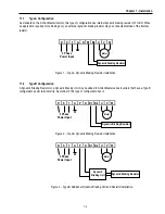
Common Features Specification
Control Method
V/F Control,
Sensorless Vector Control (Speed/Torque), Sensored Vector Control (Speed/Torque) Selectable
Frequency Setting
Resolution
Digital Reference: 0.01 Hz (Below 100 Hz), 0.1 Hz (Over 100 Hz)
Analog Reference: 0.03 Hz / 60 Hz
Frequency Accuracy
Digital: 0.01 % of Max. Output Frequency
Analog: 0.1 % of Max. Output Frequency
V/F Ratio
Linear, Square Pattern, User V/F
Overload Capacity
150 % of Rated Current for 1 Min., 200% of Rated Current for 0.5 sec. (Characteristic is Inversely
Proportional to Time)
CONT
ROL
Torque Boost
Manual Torque Boost (0 ~ 20 %), Auto Torque Boost
Operation Method
Key / Terminal / Communication Operation
Frequency Setting
Analog: 0 ~ 10V / 4 ~ 20mA / Additional ports (VR: +12V, 10mA, V2: 0-10V) for Sub-Boards
Digital: Keypad
Start Signal
Forward, Reverse
Multi-Step
Up to 8 Speeds can be Set (Use Multi-Function Terminal)
Multi Step
Accel/Decel Time
0 ~ 6,000 sec, Up to 4 Types can be Set and Selectable for Each Setting (Use Multi- Function
Terminal)
Accel/Decel Pattern: Linear, U-Curve, S-Curve Selectable
OP
ER
AT
IO
N
Input S
ignal
Emergency Stop
Instantly Interrupts the Inverter Output
5
Refer to Chapter 7 Options for DBU and DB Resistors
Summary of Contents for 30 HP30
Page 6: ......
Page 12: ......
Page 16: ...Chapter 1 Installation 1 4 BLANK ...
Page 18: ...Chapter 1 Installation 1 6 BLANK ...
Page 28: ...Chapter 1 Installation 1 16 Notes ...
Page 39: ...Chapter 2 Operation 2 11 Notes ...
Page 40: ......
Page 46: ......
Page 60: ...Chapter 4 Operation Examples 4 14 Notes ...
Page 83: ...Chapter 5 Parameter List 5 23 Notes ...
Page 84: ......
Page 92: ...Chapter 6 Parameter Description DRV 6 8 Notes ...
Page 105: ......
Page 106: ...Chapter 6 Parameter description FU1 6 14 Notes ...
Page 126: ...Chapter 6 Parameter Description FU2 6 34 Notes ...
Page 144: ...Chapter 6 Parameter Description I O 6 52 Notes ...
Page 162: ......
Page 188: ...Chapter 7 Options 7 26 Type 1 Max 400 Watt Type 2 Max 600 Watt A ...
Page 189: ...Chapter 7 Options 7 27 Type 3 ...
Page 194: ......
Page 204: ......
Page 210: ......


