


Chapter 6 - Parameter Description [I/O]
6-36
This is the filtering time constant for ‘I’ signal input. If the ‘I’
signal is affected by noise causing unstable operation of
the inverter, increase this value. Increasing this value
makes response time slower.
This is the minimum current of the ‘I’ input at which inverter
outputs minimum frequency.
This is the inverter output minimum frequency when there
is minimum current (I/O-07) on the ‘I’ terminal.
This is the maximum current of the ‘I’ input at which
inverter outputs maximum frequency.
This is the inverter output maximum frequency when there
is the maximum current (I/O-09) on the ‘I’ terminal.
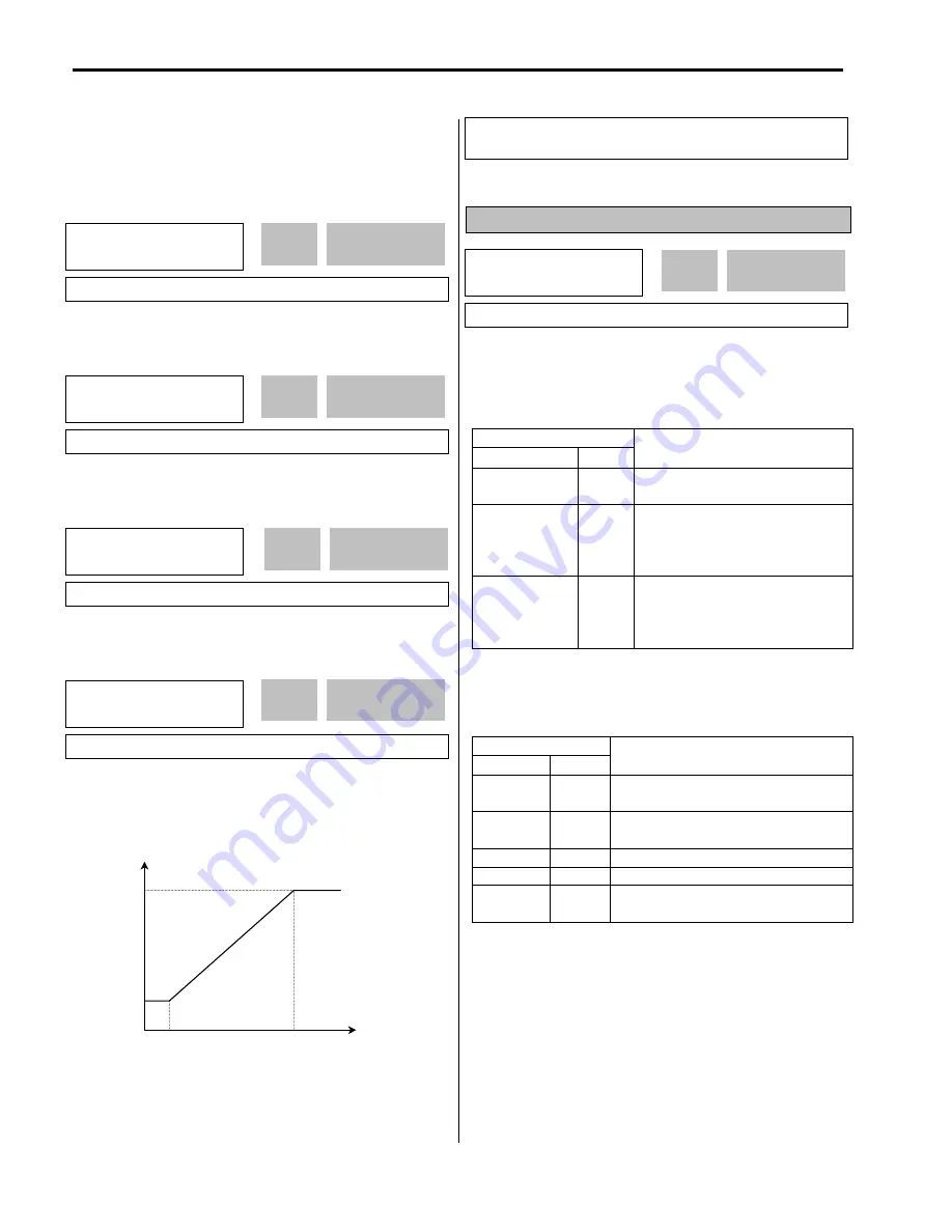
[Reference Frequency vs. Analog Current Input, I (4 to 20mA)]
I/O-11: Criteria for Analog Input Signal Loss
This is to set the criteria for analog input signal loss when
DRV-04 [Frequency Mode] is set to ‘V1’, ‘I’ or ‘V1+I’.
Following table shows the setting value.
Setting Range
LCD 7-Seg
Description
None
0
Does not check the analog input
signal.
half of x1
1
The inverter determines that the
frequency reference is lost when the
analog input signal is less than half of
the minimum value (I/O-02 or I/O-07).
below x1
2
The inverter determines that the
frequency reference is lost when the
analog input signal is less than the
minimum value (I/O-02 or I/O-07).
When the analog input signal is lost, inverter displays the
following table.
Setting Range
LCD 7-Seg
Description
LOP
LP
Loss of frequency reference from Option
Board (DPRAM time out)
LOR
LR
Loss of frequency reference from Option
Board (Communication fault)
LOV
LV
Loss of analog input signal, V1
LOI
LI
Loss of analog input signal, I
LOX
LX
Loss of frequency reference from Sub-
Board, V2 or ENC
Related Functions:
I/O-48 [Lost command] selects the
operation after determining the loss of frequency reference.
I/O
►
I curr x1
07 4.00 mA
4.00
07
Factory Default:
4.00 mA
4.00
I/O
►
I freq y1
08 0.00 Hz
0.00
08
Factory Default:
0.00 Hz
0.00
I/O
►
I curr x2
09 20.00 mA
Factory Default:
20.00 mA
20.00
I/O
►
I freq y2
10 60.00 Hz
60.00
10
Factory Default:
60.00 Hz
60.00
Reference Frequency
I/O-10
Analog Voltage
Input (V1)
I/O-08
I/O-07 I/O-09
Related Functions:
DRV-04 [Frequency Mode]
FU1-20 [Maximum Frequency]
I/O
►
Wire broken
11 None
0
11
Factory Default:
None
0
20.00
09
Summary of Contents for 30 HP30
Page 6: ......
Page 12: ......
Page 16: ...Chapter 1 Installation 1 4 BLANK ...
Page 18: ...Chapter 1 Installation 1 6 BLANK ...
Page 28: ...Chapter 1 Installation 1 16 Notes ...
Page 39: ...Chapter 2 Operation 2 11 Notes ...
Page 40: ......
Page 46: ......
Page 60: ...Chapter 4 Operation Examples 4 14 Notes ...
Page 83: ...Chapter 5 Parameter List 5 23 Notes ...
Page 84: ......
Page 92: ...Chapter 6 Parameter Description DRV 6 8 Notes ...
Page 105: ......
Page 106: ...Chapter 6 Parameter description FU1 6 14 Notes ...
Page 126: ...Chapter 6 Parameter Description FU2 6 34 Notes ...
Page 144: ...Chapter 6 Parameter Description I O 6 52 Notes ...
Page 162: ......
Page 188: ...Chapter 7 Options 7 26 Type 1 Max 400 Watt Type 2 Max 600 Watt A ...
Page 189: ...Chapter 7 Options 7 27 Type 3 ...
Page 194: ......
Page 204: ......
Page 210: ......


