


Chapter 6 - Parameter Description [I/O]
6-41
[XCEL stop]
Inverter stops accelerating and decelerating when this
terminal is ON.
[P Gain2]
This function is used to change P-Gain during PID
operation. When this terminal is ON, PID controller
changes P-Gain with PID P2-Gian set in FU2-59.
Refer to PID Control Block Diagram.
[SEQ-L, SEQ-M, SEQ-H]
These functions are used for Auto drive (I/O-50).
Five different sequences can be selected according to the
combination of these terminals. Eight step frequencies,
Accel/Decel time and steady speed time can be set for
each sequence. The following table shows the sequence
of selection.
Step
Frequency
Parameter
Code
Speed-H
(P3)
Speed-M
(P2)
Speed-L
(P1)
Sequence
1
0 0 1
Sequence
2
0 1 0
Sequence
3
1 0 0
Sequence
4
0 1 1
Sequence 5
I/O-50 ~
I/O-84
1 0 1
0: OFF, 1: ON
☞
Note:
The inverter stops after finishing all steps of that
sequence once the Auto (Sequence) operation is started.
To stop the inverter during sequence operation, use ‘BX’
terminal on the control terminal strip.
[Manual]
This is used to exchange the operation mode of inverter
from Auto (Sequence) to manual operation.
DRV-03 [Drive Mode] and DRV-04 [Frequency Mode] are
applied when the mode has been changed.
☞
Note:
This function can be used only when the inverter is
stopped.
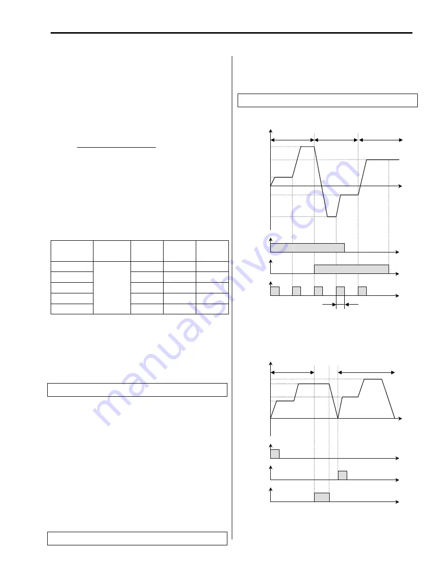
[Go step]
This is used to trigger the next step in a sequence of Auto-
B operation.
[Hold step]
This is used to hold the last step frequency in Auto-A
operation.
[‘Go step’ in Auto-B Operation]
[‘Hold step’ in Auto-A Operation]
Related Functions:
I/O-51 ~ I/O-84 [Sequence Operation]
Related Functions:
I/O-51 ~ I/O-84 [Sequence Operation]
Related Functions:
I/O-51 ~ I/O-84 [Sequence Operation]
Time
P1-CM
‘SEQ-L’
ON
Output Frequency
Time
ON
Time
ON
Time
P2-CM
‘SEQ-M’
P3-CM
‘Go step’
ON
ON
ON
ON
Minimum 100msec
SEQ1 / 2F
SEQ2 / 2F
SEQ1 / 1F
SEQ3 / 2F
SEQ3 / 1F
Sequence 1
Sequence 3
Sequence 2
P1-CM
‘SEQ-L’
Output Frequency
Time
Time
Time
P2-CM
‘SEQ-M’
P3-CM
‘Hold step’
ON
SEQ2 / 2F
SEQ1 / 2F
SEQ2 / 1F
SEQ1 / 1F
Sequence 1
Sequence 2
ON
ON
Time
Summary of Contents for 30 HP30
Page 6: ......
Page 12: ......
Page 16: ...Chapter 1 Installation 1 4 BLANK ...
Page 18: ...Chapter 1 Installation 1 6 BLANK ...
Page 28: ...Chapter 1 Installation 1 16 Notes ...
Page 39: ...Chapter 2 Operation 2 11 Notes ...
Page 40: ......
Page 46: ......
Page 60: ...Chapter 4 Operation Examples 4 14 Notes ...
Page 83: ...Chapter 5 Parameter List 5 23 Notes ...
Page 84: ......
Page 92: ...Chapter 6 Parameter Description DRV 6 8 Notes ...
Page 105: ......
Page 106: ...Chapter 6 Parameter description FU1 6 14 Notes ...
Page 126: ...Chapter 6 Parameter Description FU2 6 34 Notes ...
Page 144: ...Chapter 6 Parameter Description I O 6 52 Notes ...
Page 162: ......
Page 188: ...Chapter 7 Options 7 26 Type 1 Max 400 Watt Type 2 Max 600 Watt A ...
Page 189: ...Chapter 7 Options 7 27 Type 3 ...
Page 194: ......
Page 204: ......
Page 210: ......


