


Chapter 6 - Parameter Description [I/O]
6-43
I/O-21 ~ I/O-24: Step Frequency 4, 5, 6, 7
□
□
□
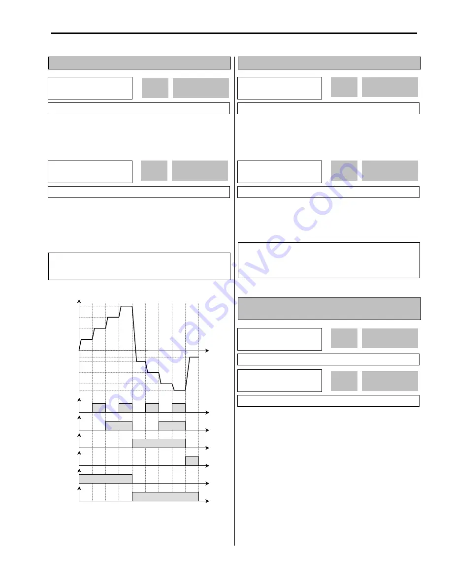
These codes set the step frequencies. These frequencies
are applied when the multi-function input terminals (P1, P2,
P3) select the step. See [Speed-L, Speed-M, Speed-H] in
I/O-12 ~ I/O-14.
[‘JOG’ and ‘Multi-Step’ Operation]
I/O-25 ~ I/O-38: 1
st
~ 7
th
Accel/Decel Time
□
□
□
These codes are applied when the multi-function input
terminals (P1, P2, P3) select the Accel/Decel time. See
[XCEL-L, XCEL-M, XCEL-H] in I/O-12 ~ I/O-14.
I/O-40: FM (Frequency Meter) Output
I/O-41: FM Adjustment
Frequency meter displays the inverter output Frequency,
Current, Voltage and DC link voltage with pulse signals on
the FM terminal. The average ranges from 0V to 10V. I/O-
41 is used to adjust the FM value.
[Frequency]
FM terminal outputs inverter output frequency. The output
value is determined by,
FM Output Voltage = (Output freq. / Max. freq.) × 10V ×
IO-41 / 100
I/O
►
Step freq-4
21 40.00 Hz
40.00
21
Factory Default:
40.00 Hz
40.00
I/O
►
Step freq-7
24 30.00 Hz
30.00
24
Factory Default:
30.00 Hz
30.00
Related Functions:
DRV-05 ~ DRV-07 [Step Frequency 1 ~ 3]
I/O-12 ~ I/O-14 [Multi-function inputs]
I/O-17 [Filtering Time Constant]
I/O
►
Acc time-1
25 20.0 sec
20.00
25
Factory Default:
20.0 sec
20.0
I/O
►
Dec time-7
38 20.0 sec
20
38
Factory Default:
20.0 sec
20.0
Related Functions:
DRV-01 ~ DRV-02 [Accel/Decel Time]
FU2-70 [Reference Freq. for Accel/Decel]
FU2-71 [Accel/Decel Time Scale]
I/O-12 ~ I/O-14 [Multi-function inputs]
I/O
►
FM mode
40 Frequency
0
40
Factory Default:
Frequency
0
I/O
►
FM Adjust
41 100 %
100
41
Factory Default:
100 %
100
P1-CM
ON
Output Frequency
Time
Time
P2-CM
Time
P3-CM
Time
Speed 1
JOG-CM
Time
FX-CM
Time
RX-CM
Time
ON
ON
ON
ON
ON
ON
ON
ON
ON
Speed 0
Speed 2
Speed 3
Speed 4
Speed 5
Speed 6
Speed 7
JOG
Summary of Contents for 30 HP30
Page 6: ......
Page 12: ......
Page 16: ...Chapter 1 Installation 1 4 BLANK ...
Page 18: ...Chapter 1 Installation 1 6 BLANK ...
Page 28: ...Chapter 1 Installation 1 16 Notes ...
Page 39: ...Chapter 2 Operation 2 11 Notes ...
Page 40: ......
Page 46: ......
Page 60: ...Chapter 4 Operation Examples 4 14 Notes ...
Page 83: ...Chapter 5 Parameter List 5 23 Notes ...
Page 84: ......
Page 92: ...Chapter 6 Parameter Description DRV 6 8 Notes ...
Page 105: ......
Page 106: ...Chapter 6 Parameter description FU1 6 14 Notes ...
Page 126: ...Chapter 6 Parameter Description FU2 6 34 Notes ...
Page 144: ...Chapter 6 Parameter Description I O 6 52 Notes ...
Page 162: ......
Page 188: ...Chapter 7 Options 7 26 Type 1 Max 400 Watt Type 2 Max 600 Watt A ...
Page 189: ...Chapter 7 Options 7 27 Type 3 ...
Page 194: ......
Page 204: ......
Page 210: ......


