Chapter 6 - Parameter Description [I/O]
6-48
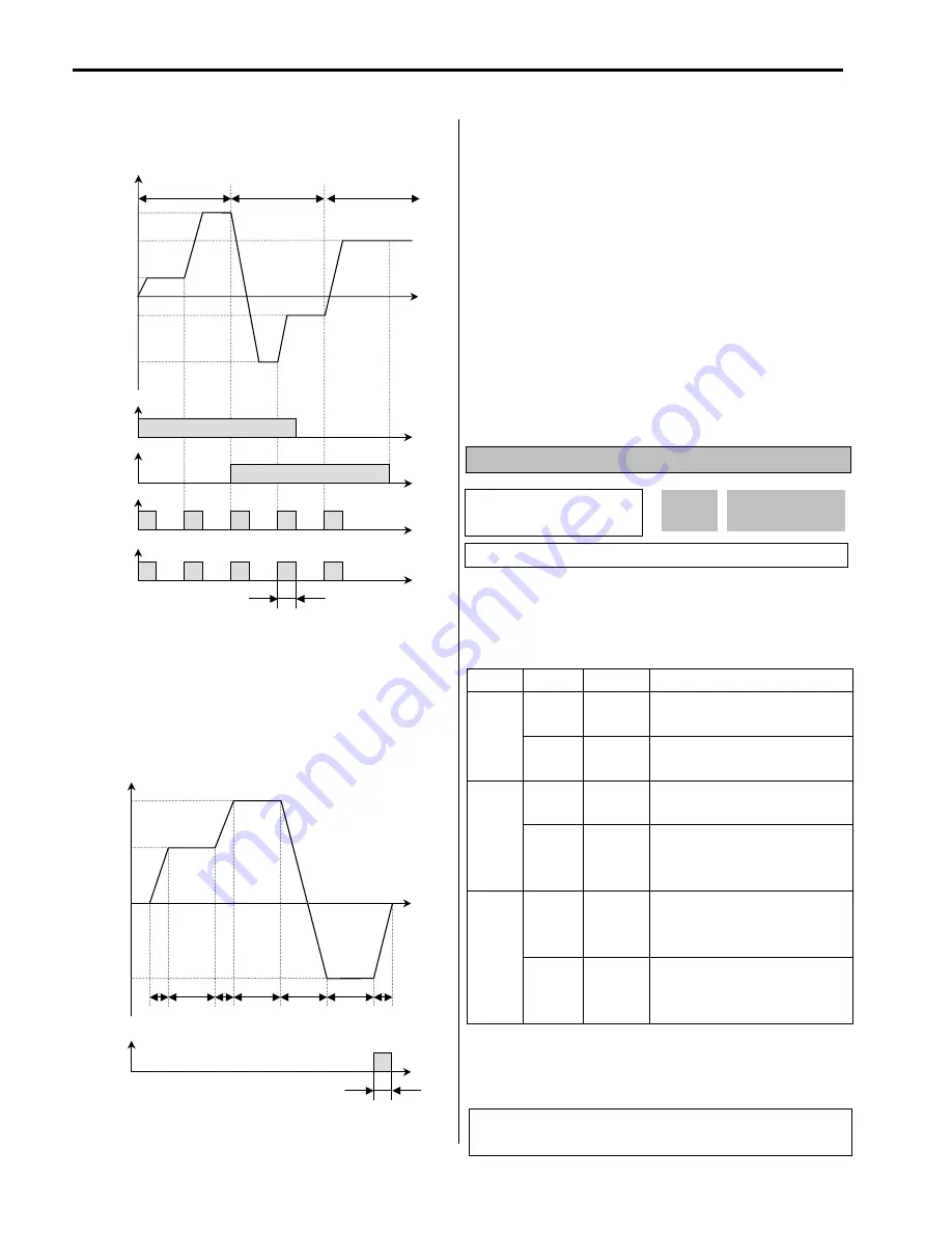
[AXA-AXC configured as ‘Step pulse’]
[Seq pulse]
When Auto (Sequence) operation is selected in I/O-50,
AXA-AXC outputs pulse signals on the last step.
[AXA-AXC configured as ‘Step pulse’]
[Ready]
AXA-AXC is CLOED when the inverter is ready to run.
[Trv. ACC]
CLOSED when output frequency reaches Accel frequency.
[Trv. DEC]
CLOSED when output frequency reaches Decel frequency.
[MMC]
Automatically set to ‘MMC’ when ‘MMC’ is selected in
APP-01.
[Zspd Dect]
0 Rpm detection signal during vector control
[Torq Dect]
Torque detection signal during vector and sensorless control.
I/O-45: Fault Output Relay (30A, 30B, 30C)
This function is used to allow the fault output relay to
operate when a fault occurs. The output relay terminal is
30A, 30B, 30C where 30A-30C is a normally open contact
and 30B-30C is a normally closed contact.
Bit Setting Display
Description
0 000
Fault output relay does not
operate at ‘Low voltage’ trip.
Bit 0
(LV)
1 001
Fault output relay operates at
‘Low voltage’ trip.
0 000
Fault output relay does not
operate at any fault.
Bit 1
(Trip)
1 010
Fault output relay operates at
any fault
except
‘Low voltage’
and ‘BX’ (inverter disable) fault.
0 000
Fault output relay does not
operate regardless of the retry
number.
Bit 2
(Retry)
1 100
Fault output relay operates when
the retry number set in FU2-26
decreases to 0 by faults.
☞
When several faults occurred at the same time, Bit 0 has
the first priority.
Output Frequency
Time
Seq# / 2F
Seq# / 1F
Seq# / 3F
1T 1S
2T
2S
3T
3S
1D
(Forward)
2D
(Forward)
3D
(Reverse)
DRV-02
AXA-AXC
‘Step pulse’
Time
ON
Minimum 100msec
I/O
►
Relay mode
45 010
010
45
Factory Default:
010
010
Related Functions:
DRV-12 [Fault Display]
FU2-26 [Retry number]
AXA-AXC
‘Step pulse’
P1-CM
‘SEQ-L’
ON
Output Frequency
Time
ON
Time
ON
Time
P2-CM
‘SEQ-M’
P3-CM
‘Go step’
ON
ON
ON
ON
SEQ1 / 2F
SEQ2 / 2F
SEQ1 / 1F
SEQ3 / 2F
SEQ3 / 1F
Sequence 1
Sequence 3
Sequence 2
ON
Time
ON
ON
ON
ON
Minimum 100msec
Time
Summary of Contents for 30 HP30
Page 6: ......
Page 12: ......
Page 16: ...Chapter 1 Installation 1 4 BLANK ...
Page 18: ...Chapter 1 Installation 1 6 BLANK ...
Page 28: ...Chapter 1 Installation 1 16 Notes ...
Page 39: ...Chapter 2 Operation 2 11 Notes ...
Page 40: ......
Page 46: ......
Page 60: ...Chapter 4 Operation Examples 4 14 Notes ...
Page 83: ...Chapter 5 Parameter List 5 23 Notes ...
Page 84: ......
Page 92: ...Chapter 6 Parameter Description DRV 6 8 Notes ...
Page 105: ......
Page 106: ...Chapter 6 Parameter description FU1 6 14 Notes ...
Page 126: ...Chapter 6 Parameter Description FU2 6 34 Notes ...
Page 144: ...Chapter 6 Parameter Description I O 6 52 Notes ...
Page 162: ......
Page 188: ...Chapter 7 Options 7 26 Type 1 Max 400 Watt Type 2 Max 600 Watt A ...
Page 189: ...Chapter 7 Options 7 27 Type 3 ...
Page 194: ......
Page 204: ......
Page 210: ......


