


Chapter 6 - Parameter Description [EXT]
6-56
EXT-16: Encoder Pulse Number – Sub-B
This code sets the encoder pulse per rotation of encoder.
EXT-17: Filtering Time Constant for Pulse Input
Signal – Sub-B
This is the filtering time constant of pulse input signal. This
is used to make the inverter respond slowly to the pulse
input signal when the EXT-14 is set to ‘Reference’.
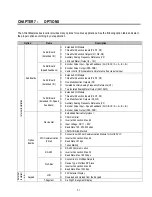
EXT-18 ~ EXT-21: Pulse Input Signal Adjustment –
Sub-B
This is used to adjust the pulse input signal when the pulse
input through Sub-B board references the frequency. This
function is applied when EXT-14 is set to ‘Reference’.
Reference Frequency versus Analog Voltage Input Curve
can be made by four parameters of EXT-18 ~ EXT-21.
This is the minimum pulse frequency at which the inverter
outputs minimum frequency.
This is the minimum frequency the inverter outputs when
there is the minimum pulse frequency (EXT-18).
This is the maximum pulse frequency at which the inverter
outputs maximum frequency.
This is the maximum frequency the inverter outputs when
there is the maximum pulse frequency (EXT-20).
[Reference Frequency vs. Pulse Input]
EXT-22 ~ EXT-23: Gains for ‘Sub-B’ Board
This is the proportional gain when the EXT-14 is set to
‘Feed-back’.
This is the integral gain when the EXT-14 is set to ‘Feed-
back’.
EXT
►
F pulse num
16 1024
1024
16
Factory Default:
1024
1024
EXT
►
F filter
17 10 ms
10
17
Factory Default:
10 ms
10
EXT
►
F pulse x1
18 0.0 kHz
0.0
18
Factory Default:
0.0 kHz
0.0
EXT
►
F freq y1
19 0.00 Hz
0.00
19
Factory Default:
0.00 Hz
0.00
EXT
►
F pulse x2
20 10.0 kHz
10.0
20
Factory Default:
10.0 kHz
10.0
EXT
►
F freq y2
21 60.00 Hz
60.00
21
Factory Default:
60.00 Hz
60.00
EXT
►
PG P-gain
22 3000
3000
22
Factory Default:
3000
3000
EXT
►
PG I-gain
23 300
300
23
Factory Default:
300
300
Reference Frequency
EXT-21
Pulse Input
(0 to 10 kHz)
EXT-19
EXT-18
EXT-20
Summary of Contents for 30 HP30
Page 6: ......
Page 12: ......
Page 16: ...Chapter 1 Installation 1 4 BLANK ...
Page 18: ...Chapter 1 Installation 1 6 BLANK ...
Page 28: ...Chapter 1 Installation 1 16 Notes ...
Page 39: ...Chapter 2 Operation 2 11 Notes ...
Page 40: ......
Page 46: ......
Page 60: ...Chapter 4 Operation Examples 4 14 Notes ...
Page 83: ...Chapter 5 Parameter List 5 23 Notes ...
Page 84: ......
Page 92: ...Chapter 6 Parameter Description DRV 6 8 Notes ...
Page 105: ......
Page 106: ...Chapter 6 Parameter description FU1 6 14 Notes ...
Page 126: ...Chapter 6 Parameter Description FU2 6 34 Notes ...
Page 144: ...Chapter 6 Parameter Description I O 6 52 Notes ...
Page 162: ......
Page 188: ...Chapter 7 Options 7 26 Type 1 Max 400 Watt Type 2 Max 600 Watt A ...
Page 189: ...Chapter 7 Options 7 27 Type 3 ...
Page 194: ......
Page 204: ......
Page 210: ......


