


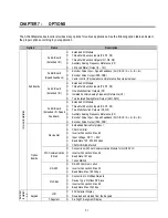
Chapter 6 - Parameter Description [APP]
6-62
6.6 Application Group [APP]
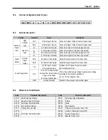
APP-00: Jump to desired code #
Jumping directly to any parameter code can be
accomplished by entering the desired code number. This
code is available only with LCD keypad.
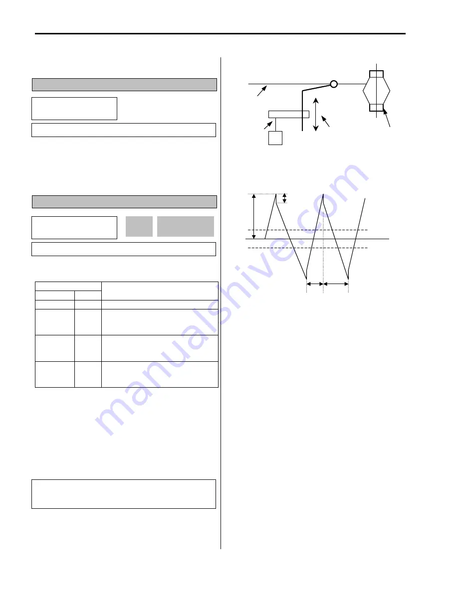
APP-01: Application Mode Selection
This code sets the application mode.
Setting Range
LCD 7-Seg
Description
None
0
Application mode is not selected.
Traverse
1
Traverse mode is selected in application
group. Related functions (APP-02~07) are
displayed.
MMC
2
MMC (Multi-Motor Control) mode is
selected in application group. Related
functions (APP-08~31) are displayed.
DRAW
3
DRAW mode is selected in application
group. Related functions (APP-32~33) are
displayed.
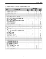
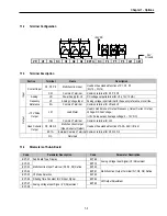
[Traverse]:
This is a mechanism to wind thread to an
intended shape on a reel with a rotary motion and
reciprocation. Adjusting the speed of mechanical
reciprocation can make different shapes of thread reel.
The following figure shows an example. The guide should
move with low speed at the center of the reel and fast at
the edge of the reel.
[An example of Traverse Operation]
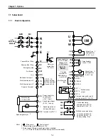
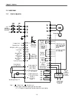
[Traverse Operation Pattern]
[MMC]:
The ‘PID’ control should be selected in FU2-47 to
use this function.
♦
One inverter can control multiple motors. This function
is often used when controlling the amount and pressure of
flow in fans or pumps. Built-in PI controller controls a main
motor after receiving process control value and keeps the
control value constant by connecting auxiliary motors to
commercial line when needed.
♦
In case that flow amount or flow pressure is beyond or
below the reference so the main drive cannot control by
itself, auxiliary motors are automatically turned on/off.
Maximum four (Q1~3 and Aux. output) auxiliary motors
can be run. Each Starting and Stop Frequency should be
set to four auxiliary motors.
♦
Auto Change can be selected to automatically switch
the order of the running motors for keeping motor run-time
constant. Set mode ‘1’ for automatic changing of auxiliary
motors only and set mode ‘2’ for automatic changing of all
APP
►
Jump code
00 1
Factory Default:
1
APP
►
App. mode
01 None
0
01
Factory Default:
None
0
Traverse
Rotary
Motion
Thread
Traverse
Reciprocation
(Mechanical)
Thread
(Constant
Speed)
APP-05
Traverse Dec
APP-03
Trv. Scr
APP-04
Traverse Acc
APP-06
Offset-High
APP-07
Offset-Low
Reference
Speed
APP-02
Trv. Amp
Related Functions:
APP-02 to APP-07 [Traverse Parameters]
I/O-12 to I/O-14 [Multi-Function Input]
EXT-30 to EXT-32 [Multi-Function Output]
Summary of Contents for 30 HP30
Page 6: ......
Page 12: ......
Page 16: ...Chapter 1 Installation 1 4 BLANK ...
Page 18: ...Chapter 1 Installation 1 6 BLANK ...
Page 28: ...Chapter 1 Installation 1 16 Notes ...
Page 39: ...Chapter 2 Operation 2 11 Notes ...
Page 40: ......
Page 46: ......
Page 60: ...Chapter 4 Operation Examples 4 14 Notes ...
Page 83: ...Chapter 5 Parameter List 5 23 Notes ...
Page 84: ......
Page 92: ...Chapter 6 Parameter Description DRV 6 8 Notes ...
Page 105: ......
Page 106: ...Chapter 6 Parameter description FU1 6 14 Notes ...
Page 126: ...Chapter 6 Parameter Description FU2 6 34 Notes ...
Page 144: ...Chapter 6 Parameter Description I O 6 52 Notes ...
Page 162: ......
Page 188: ...Chapter 7 Options 7 26 Type 1 Max 400 Watt Type 2 Max 600 Watt A ...
Page 189: ...Chapter 7 Options 7 27 Type 3 ...
Page 194: ......
Page 204: ......
Page 210: ......


