


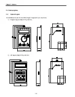
Chapter 7 - Options
7-3
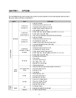
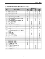
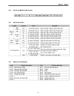
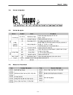
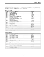
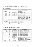
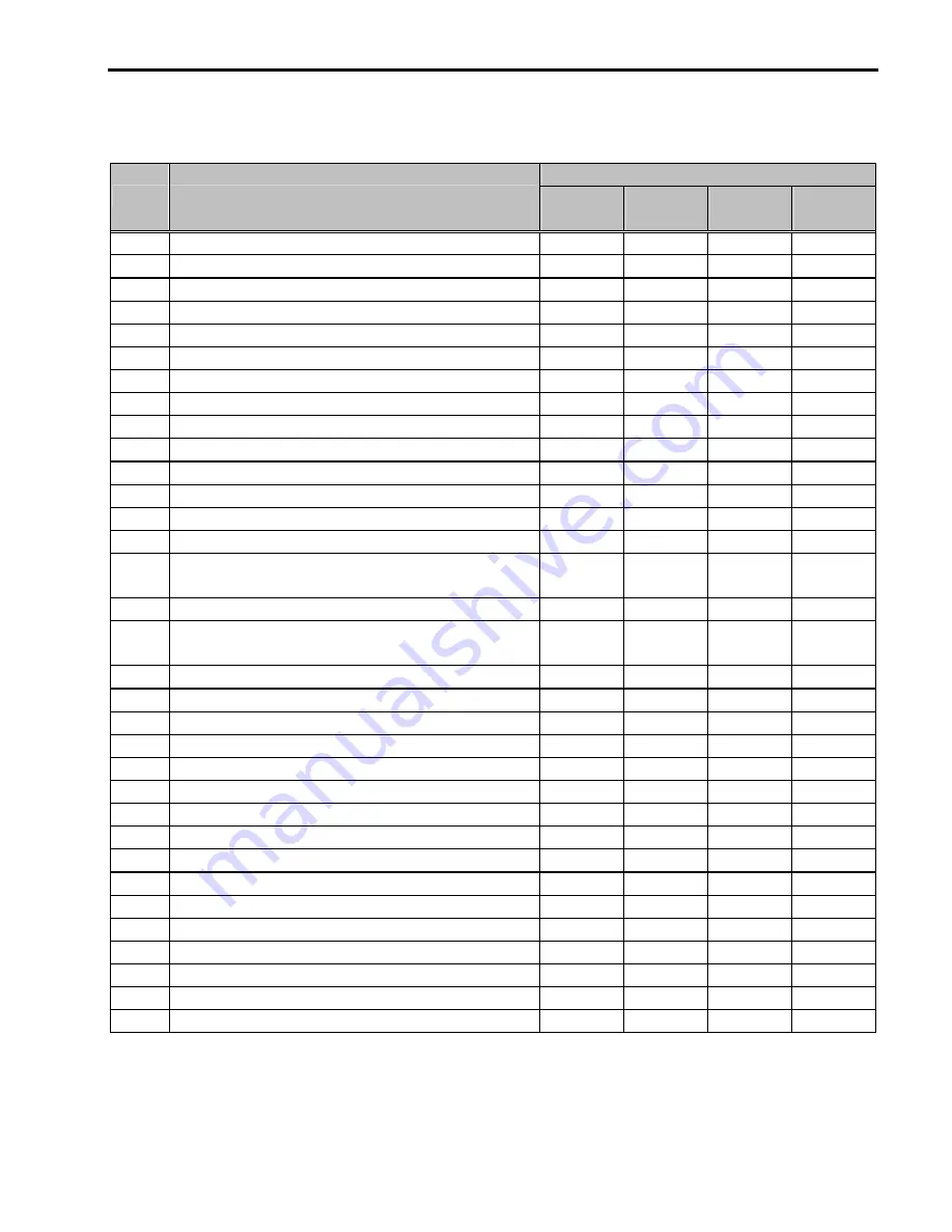
The following table shows the Sub-Board Selection Guide According To Functions.
Sub-Board Type
Code
Function Description
SUB-A
Board
SUB-B
Board
SUB-C
Board
SUB-D
Board
EXT-02
Multi-Function Input Terminal ‘P4’
√
√
√
√
√
√
√
√
√
√
√
√
EXT-03
Multi-Function Input Terminal ‘P5’
√
√
√
√
√
√
√
√
√
√
√
√
EXT-04
Multi-Function Input Terminal ‘P6’
√
√
√
√
√
√
√
√
√
√
√
√
EXT-05
V2 Mode Selection
√
√
√
√
√
√
√
√
√
√
√
√
EXT-06
Filtering Time Constant for V2 Input Signal
√
√
√
√
√
√
√
√
√
√
√
√
EXT-07
V2 Input Minimum Voltage
√
√
√
√
√
√
√
√
√
√
√
√
EXT-08
Frequency Corresponding to V2 Input Minimum Voltage
√
√
√
√
√
√
√
√
√
√
√
√
EXT-09
V2 Input Maximum Voltage
√
√
√
√
√
√
√
√
√
√
√
√
EXT-10
Frequency Corresponding to V2 Input Maximum Voltage
√
√
√
√
√
√
√
√
√
√
√
√
EXT-14
Usage for Pulse Input Signal
√
√
√
√
√
√
√
√
EXT-15
Pulse Input Signal Selection
√
√
√
√
√
√
√
√
EXT-16
Encoder Pulse Selection
√
√
√
√
√
√
√
√
EXT-17
Filtering Time Constant for Pulse Input Signal
√
√
√
√
√
√
√
√
EXT-18
Pulse Input Minimum Frequency
√
√
√
√
√
√
√
√
EXT-19
Frequency Output corresponding to Pulse Input Minimum
Frequency
√
√
√
√
√
√
√
√
EXT-20
Pulse Input Maximum Frequency
√
√
√
√
√
√
√
√
EXT-21
Frequency Output corresponding to Pulse Input Maximum
Frequency
√
√
√
√
√
√
√
√
EXT-22
P-Gain for PG Option
√
√
√
√
√
√
√
√
EXT-23
I-Gain for PG Option
√
√
√
√
√
√
√
√
EXT-24
Slip Frequency for PG Option
√
√
√
√
√
√
√
√
EXT-25
P-Gain for (Sensored) Vector_SPD
√
√
√
√
EXT-26
I-Gain for (Sensored) Vector_SPD
√
√
√
√
EXT-27
Forward Torque Limit
√
√
√
√
EXT-28
Reverse Torque Limit
√
√
√
√
EXT-30
Multi-function Output Terminal ‘Q1’
√
√
√
√
√
√
√
√
√
√
√
√
EXT-31
Multi-function Output Terminal ‘Q2’
√
√
√
√
√
√
√
√
EXT-32
Multi-function Output Terminal ‘Q3’
√
√
√
√
EXT-34
LM (Load Meter) Output Selection
√
√
√
√
EXT-35
LM Output Adjustment
√
√
√
√
EXT-40
AM1 (Analog Meter 1) Output Selection
√
√
√
√
EXT-41
AM1 Output Adjustment
√
√
√
√
EXT-42
AM2 (Analog Meter 2) Output Selection
√
√
√
√
EXT-43
AM2 Output Adjustment
√
√
√
√
Summary of Contents for 30 HP30
Page 6: ......
Page 12: ......
Page 16: ...Chapter 1 Installation 1 4 BLANK ...
Page 18: ...Chapter 1 Installation 1 6 BLANK ...
Page 28: ...Chapter 1 Installation 1 16 Notes ...
Page 39: ...Chapter 2 Operation 2 11 Notes ...
Page 40: ......
Page 46: ......
Page 60: ...Chapter 4 Operation Examples 4 14 Notes ...
Page 83: ...Chapter 5 Parameter List 5 23 Notes ...
Page 84: ......
Page 92: ...Chapter 6 Parameter Description DRV 6 8 Notes ...
Page 105: ......
Page 106: ...Chapter 6 Parameter description FU1 6 14 Notes ...
Page 126: ...Chapter 6 Parameter Description FU2 6 34 Notes ...
Page 144: ...Chapter 6 Parameter Description I O 6 52 Notes ...
Page 162: ......
Page 188: ...Chapter 7 Options 7 26 Type 1 Max 400 Watt Type 2 Max 600 Watt A ...
Page 189: ...Chapter 7 Options 7 27 Type 3 ...
Page 194: ......
Page 204: ......
Page 210: ......


