


Chapter 7 - Options
7-16
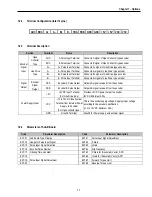
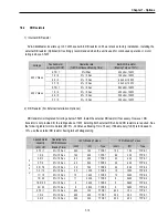
7.5.3
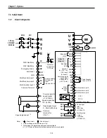
RS485 Communication
The serial interface supports operation, configuration and monitoring of inverter functions through RS485 connection.
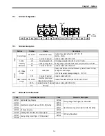
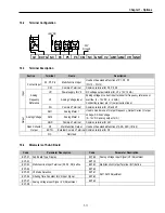
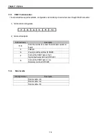
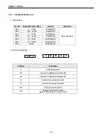
1) Terminal block configuration
P N G S T1 T2
2) Terminal Description
Terminal Name
Description
T1,T2
Short the terminal to connect the termination resistor on
board
S SHEILD
G
Power grounding terminal for RS485
P
Connect the RS485 signal - High
Signal input/output terminal for RS 485
N
Connect the RS485 signal - Low
Reference terminal for RS 485
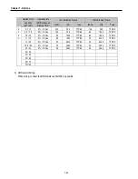
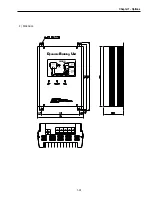
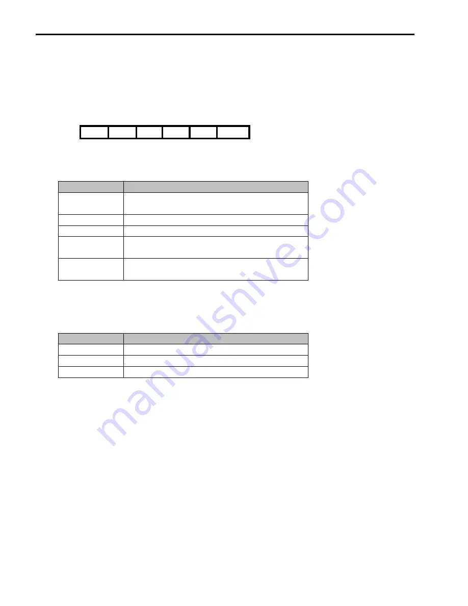
7.5.4
Remote cable
Ordering Number
Description
Remote cable - 2m
Remote cable - 3m
Remote cable - 5m
Summary of Contents for 30 HP30
Page 6: ......
Page 12: ......
Page 16: ...Chapter 1 Installation 1 4 BLANK ...
Page 18: ...Chapter 1 Installation 1 6 BLANK ...
Page 28: ...Chapter 1 Installation 1 16 Notes ...
Page 39: ...Chapter 2 Operation 2 11 Notes ...
Page 40: ......
Page 46: ......
Page 60: ...Chapter 4 Operation Examples 4 14 Notes ...
Page 83: ...Chapter 5 Parameter List 5 23 Notes ...
Page 84: ......
Page 92: ...Chapter 6 Parameter Description DRV 6 8 Notes ...
Page 105: ......
Page 106: ...Chapter 6 Parameter description FU1 6 14 Notes ...
Page 126: ...Chapter 6 Parameter Description FU2 6 34 Notes ...
Page 144: ...Chapter 6 Parameter Description I O 6 52 Notes ...
Page 162: ......
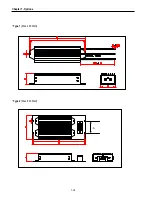
Page 188: ...Chapter 7 Options 7 26 Type 1 Max 400 Watt Type 2 Max 600 Watt A ...
Page 189: ...Chapter 7 Options 7 27 Type 3 ...
Page 194: ......
Page 204: ......
Page 210: ......


