Chapter 1 - Installation
1-14
1.8.1
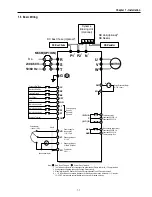
Wiring Control Terminals
Wiring Precautions
CM and 5G terminals are insulated to each other. Do not connect these terminals with each other and do not connect
these terminals to the power ground.
Use shielded wires or twisted wires for control circuit wiring, and separate these wires from the main power circuits
and other high voltage circuits.
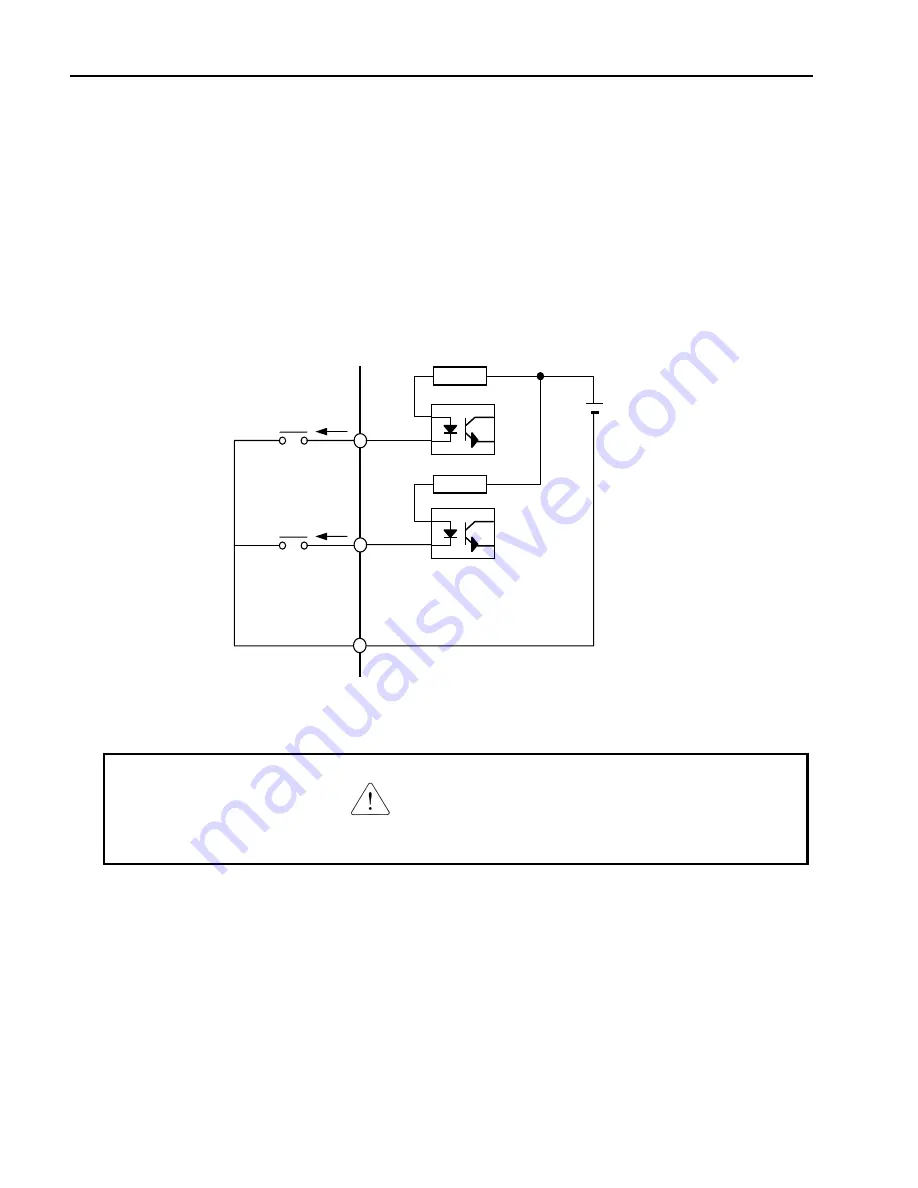
Control Circuit Terminal
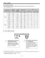
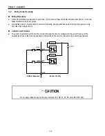
The control input terminal of the control circuit is ON when the circuit is configured to the current flows out of the
terminal, as shown in the following illustration. CM terminal is the common terminal for the contact input signals.
CAUTION
Do not apply voltage to any control input terminals (FX, RX, P1, P2, P3, JOG, BX, RST, CM).
24 VDC
FX
RX
CM
Current
Inverter Circuitry
Resistor
Resistor
External Sequence
Summary of Contents for 30 HP30
Page 6: ......
Page 12: ......
Page 16: ...Chapter 1 Installation 1 4 BLANK ...
Page 18: ...Chapter 1 Installation 1 6 BLANK ...
Page 28: ...Chapter 1 Installation 1 16 Notes ...
Page 39: ...Chapter 2 Operation 2 11 Notes ...
Page 40: ......
Page 46: ......
Page 60: ...Chapter 4 Operation Examples 4 14 Notes ...
Page 83: ...Chapter 5 Parameter List 5 23 Notes ...
Page 84: ......
Page 92: ...Chapter 6 Parameter Description DRV 6 8 Notes ...
Page 105: ......
Page 106: ...Chapter 6 Parameter description FU1 6 14 Notes ...
Page 126: ...Chapter 6 Parameter Description FU2 6 34 Notes ...
Page 144: ...Chapter 6 Parameter Description I O 6 52 Notes ...
Page 162: ......
Page 188: ...Chapter 7 Options 7 26 Type 1 Max 400 Watt Type 2 Max 600 Watt A ...
Page 189: ...Chapter 7 Options 7 27 Type 3 ...
Page 194: ......
Page 204: ......
Page 210: ......


