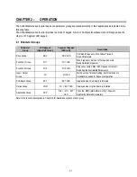
Chapter 2 - Operation
2-3
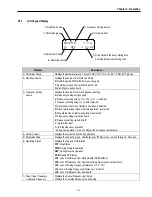
2.2.1
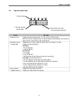
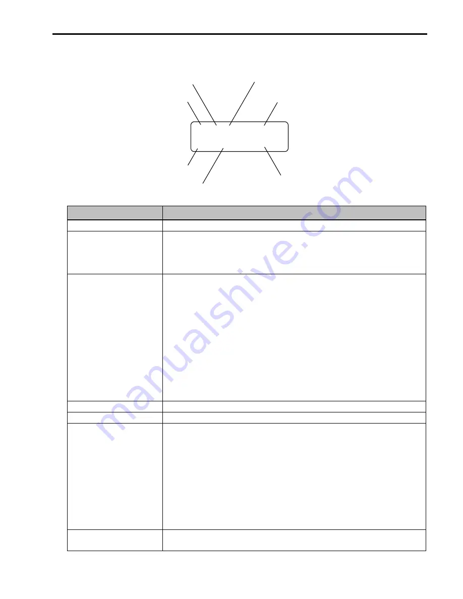
LCD Keypad Display
DRV
¢º
T/K 0.0 A
00 STP 0.00 Hz
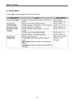
Displays
Description
1) Parameter Group
Displays the parameter group. There are DRV, FU1, FU2, I/O, EXT, COM, APP groups.
2) Run/Stop Source
Displays the source of motor Run and Stop
K
: Run/Stop using FWD, REV buttons on keypad
T
: Run/Stop using control terminal input FX, RX
O
: Run/Stop via option board
3) Frequency Setting
Source
Displays the source of command frequency setting
K
: Frequency setting using keypad
V
: Frequency setting using V1 (0 ~10V) or V1 + I terminal
I:
Frequency setting using I (4 ~ 20mA) terminal
U
: Up terminal input when Up/Down operation is selected
D
: Down terminal input when Up/Down operation is selected
S
: Stop status when Up/Down operation is selected
O
: Frequency setting via Option board
X
: Frequency setting via Sub board
J
: Jog terminal input
1 ~ 8
: Step frequency operation
* During Auto operation, 2) and 3) display the ‘sequence number/step’.
4) Output Current
Displays the Output Current during operation.
5) Parameter Code
Displays the code of a group. Use the
▲
(Up),
▼
(Down) key to move through 0~99 codes.
6) Operating Status
Displays the operation information.
STP
: Stop Status
FWD
: During Forward operation
REV
: During Reverse operation
DCB
: During DC Braking
LOP
: Loss of Reference from Option Board (DPRAM fault)
LOR
: Loss of Reference from Option Board (Communication network fault)
LOV
: Loss of Analog Frequency Reference (V1: 0~10V)
LOI
: Loss of Analog Frequency Reference (I: 4~20mA)
LOS
: Loss of Reference from Sub-Board
7) Drive Output Frequency
Command Frequency
Displays the Output Frequency during run.
Displays the Command Frequency during stop.
2) Run/Stop Source
3) Frequency Setting Source
4) Output Current
7) Drive Output Frequency During Run,
Command Frequency During Stop
6) Operating Status
5) Parameter Code
1) Parameter group
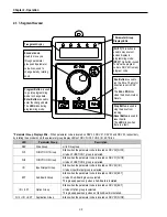
Summary of Contents for 30 HP30
Page 6: ......
Page 12: ......
Page 16: ...Chapter 1 Installation 1 4 BLANK ...
Page 18: ...Chapter 1 Installation 1 6 BLANK ...
Page 28: ...Chapter 1 Installation 1 16 Notes ...
Page 39: ...Chapter 2 Operation 2 11 Notes ...
Page 40: ......
Page 46: ......
Page 60: ...Chapter 4 Operation Examples 4 14 Notes ...
Page 83: ...Chapter 5 Parameter List 5 23 Notes ...
Page 84: ......
Page 92: ...Chapter 6 Parameter Description DRV 6 8 Notes ...
Page 105: ......
Page 106: ...Chapter 6 Parameter description FU1 6 14 Notes ...
Page 126: ...Chapter 6 Parameter Description FU2 6 34 Notes ...
Page 144: ...Chapter 6 Parameter Description I O 6 52 Notes ...
Page 162: ......
Page 188: ...Chapter 7 Options 7 26 Type 1 Max 400 Watt Type 2 Max 600 Watt A ...
Page 189: ...Chapter 7 Options 7 27 Type 3 ...
Page 194: ......
Page 204: ......
Page 210: ......

