


Chapter 2 - Operation
2-6
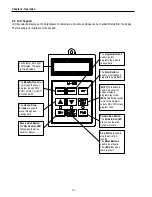
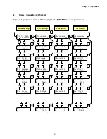
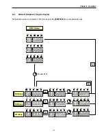
2.3 7-Segment Keypad
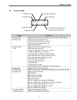
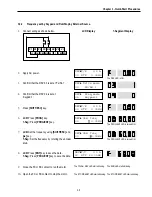
* Parameter Group Display LEDs
– When parameter code is located on DRV 20, DRV 21, DRV 22 and DRV 23, respectively,
by rotating the encoder knob, the parameter group display LEDs of DRV, FUN1, FUN2, I/O, EXT blink.
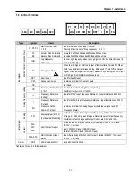
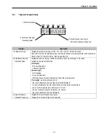
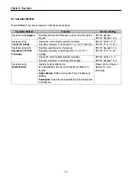
LED
Parameter Group
Description
DRV
Drive Group
Lit in Drive group.
FU1
FUNCTION 1 Group
Blinks when the parameter code is located on DRV 20 [FUN1].
Lit when FUNCTION 1 group is selected.
FU2
FUNCTION 2 Group
Blinks when the parameter code is located on DRV 21 [FUN2].
Lit when FUNCTION 2 group is selected.
I/O Input/Output
Group
Blinks when the parameter code is located on DRV 22 [I/O].
Lit when Input/Output group is selected
EXT Sub-Board
Group
Blinks when the parameter code is located on DRV 23 [EXT].
Lit when Sub-Board group is selected.
This group appears only when a Sub-Board is installed.
I/O + EXT
Option Group
Blinks when the parameter code is located on DRV 24 [EXT].
Lit when Option group is selected.
This group appears only when an Option Board is installed.
FU2 + I/O + EXT Application Group
Blinks when the parameter code is located on DRV 25 [FUN2].
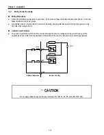
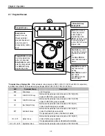
7-segment
display
Encoder knob
Used to move you
through parameter
groups and parameter
code. Also, used to
change data by rotating
knob.
Program Button
is used
to go into programming
mode to change data.
Enter Button
is used to
enter the changed data.
The
LED
blinks during
programming mode.
[SHIFT]
This button is
used to move cursor
across display in
programming mode.
[ESC]
This button is used
to move the program
code to DRV 00 from any
program code.
Run Button
is used to
run the drive. The motor
direction is set in DRV
13.
The
Run LED
blinks
when the drive Accels or
Decels.
Stop Button
is used to
stop the drive from
running.
Reset Button
is used to
reset Faults.
The
LED
blinks when
there is a fault.
* Parameter Group
Display LEDs.
Summary of Contents for 30 HP30
Page 6: ......
Page 12: ......
Page 16: ...Chapter 1 Installation 1 4 BLANK ...
Page 18: ...Chapter 1 Installation 1 6 BLANK ...
Page 28: ...Chapter 1 Installation 1 16 Notes ...
Page 39: ...Chapter 2 Operation 2 11 Notes ...
Page 40: ......
Page 46: ......
Page 60: ...Chapter 4 Operation Examples 4 14 Notes ...
Page 83: ...Chapter 5 Parameter List 5 23 Notes ...
Page 84: ......
Page 92: ...Chapter 6 Parameter Description DRV 6 8 Notes ...
Page 105: ......
Page 106: ...Chapter 6 Parameter description FU1 6 14 Notes ...
Page 126: ...Chapter 6 Parameter Description FU2 6 34 Notes ...
Page 144: ...Chapter 6 Parameter Description I O 6 52 Notes ...
Page 162: ......
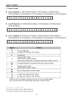
Page 188: ...Chapter 7 Options 7 26 Type 1 Max 400 Watt Type 2 Max 600 Watt A ...
Page 189: ...Chapter 7 Options 7 27 Type 3 ...
Page 194: ......
Page 204: ......
Page 210: ......


