


Chapter 3 - Quick-Start Procedures
3-5
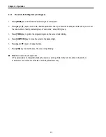
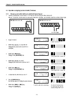
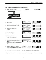
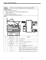
3.3.2
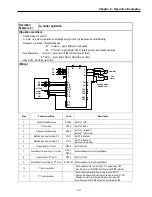
Frequency set by Keypad and Run/Stop by External Source.
1.
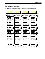
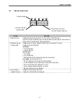
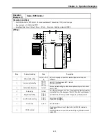
Connect wiring as shown below.
2.
Apply AC power.
3.
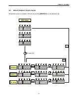
Confirm that the DRV 03 is set at ‘Fx/Rx-1’.
4.
Confirm that the DRV 04 is set at
‘Keypad-1’.
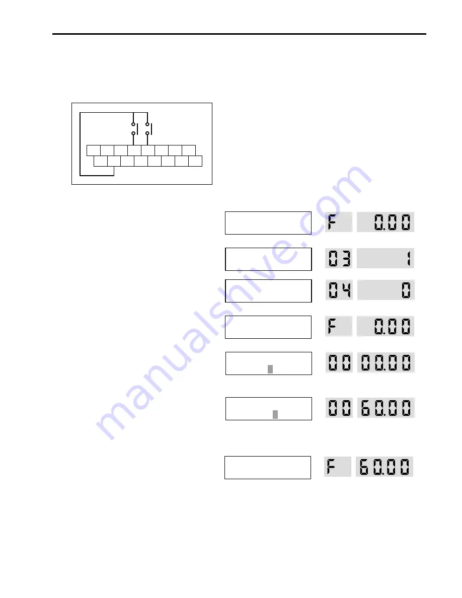
5.
Press
[SHIFT/ESC]
key.
6.
LCD:
Press
[PROG]
key.
7-Seg:
Press
[PROG/ENT]
key.
7.
LCD:
Set the frequency using
[SHIFT/ESC]
and
[
▲
]
key.
7-Seg:
Set the frequency by rotating the encoder
knob.
8.
LCD:
Press
[ENT]
key to save the data.
7-Seg:
Press [
PROG/ENT]
key to save the data.
9.
Close the FX or RX contact to run the motor.
10.
Open the FX or RX contact to stop the motor.
LCD Display
7-Segment Display
P1 P2
JOG
CM
P3 FX RX NC
CM BX
RST
I
VR VI
FM 5G
DRV
►
T/K 0.0 A
00 STP 0.00Hz
The DRV LED is ON.
DRV
►
Drive mode
03 Fx/Rx-1
DRV
►
Freq mode
04 Keypad-1
DRV
►
T/K 0.0 A
00 STP 0.00Hz
DRV
►
Cmd. freq
00 0.00Hz
The PROG/ENT LED is turned ON.
DRV
►
Cmd. freq
00 60.00Hz
The PROG/ENT LED is turned ON.
DRV
►
T/V 0.0 A
00 STP 60.00Hz
The FWD or REV LED starts blinking. The RUN LED starts blinking.
The STOP/RESET LED starts blinking. The STOP/RESET LED starts blinking.
Summary of Contents for 30 HP30
Page 6: ......
Page 12: ......
Page 16: ...Chapter 1 Installation 1 4 BLANK ...
Page 18: ...Chapter 1 Installation 1 6 BLANK ...
Page 28: ...Chapter 1 Installation 1 16 Notes ...
Page 39: ...Chapter 2 Operation 2 11 Notes ...
Page 40: ......
Page 46: ......
Page 60: ...Chapter 4 Operation Examples 4 14 Notes ...
Page 83: ...Chapter 5 Parameter List 5 23 Notes ...
Page 84: ......
Page 92: ...Chapter 6 Parameter Description DRV 6 8 Notes ...
Page 105: ......
Page 106: ...Chapter 6 Parameter description FU1 6 14 Notes ...
Page 126: ...Chapter 6 Parameter Description FU2 6 34 Notes ...
Page 144: ...Chapter 6 Parameter Description I O 6 52 Notes ...
Page 162: ......
Page 188: ...Chapter 7 Options 7 26 Type 1 Max 400 Watt Type 2 Max 600 Watt A ...
Page 189: ...Chapter 7 Options 7 27 Type 3 ...
Page 194: ......
Page 204: ......
Page 210: ......


