

Chapter 5 - Parameter List
5-3
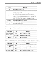
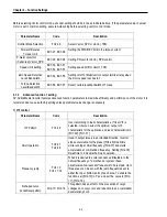
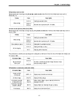
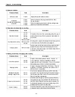
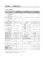
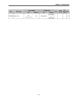
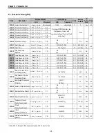
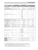
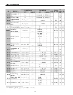
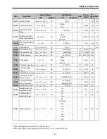
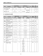
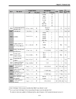
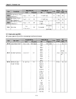
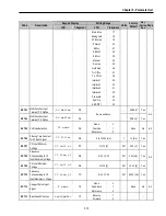
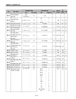
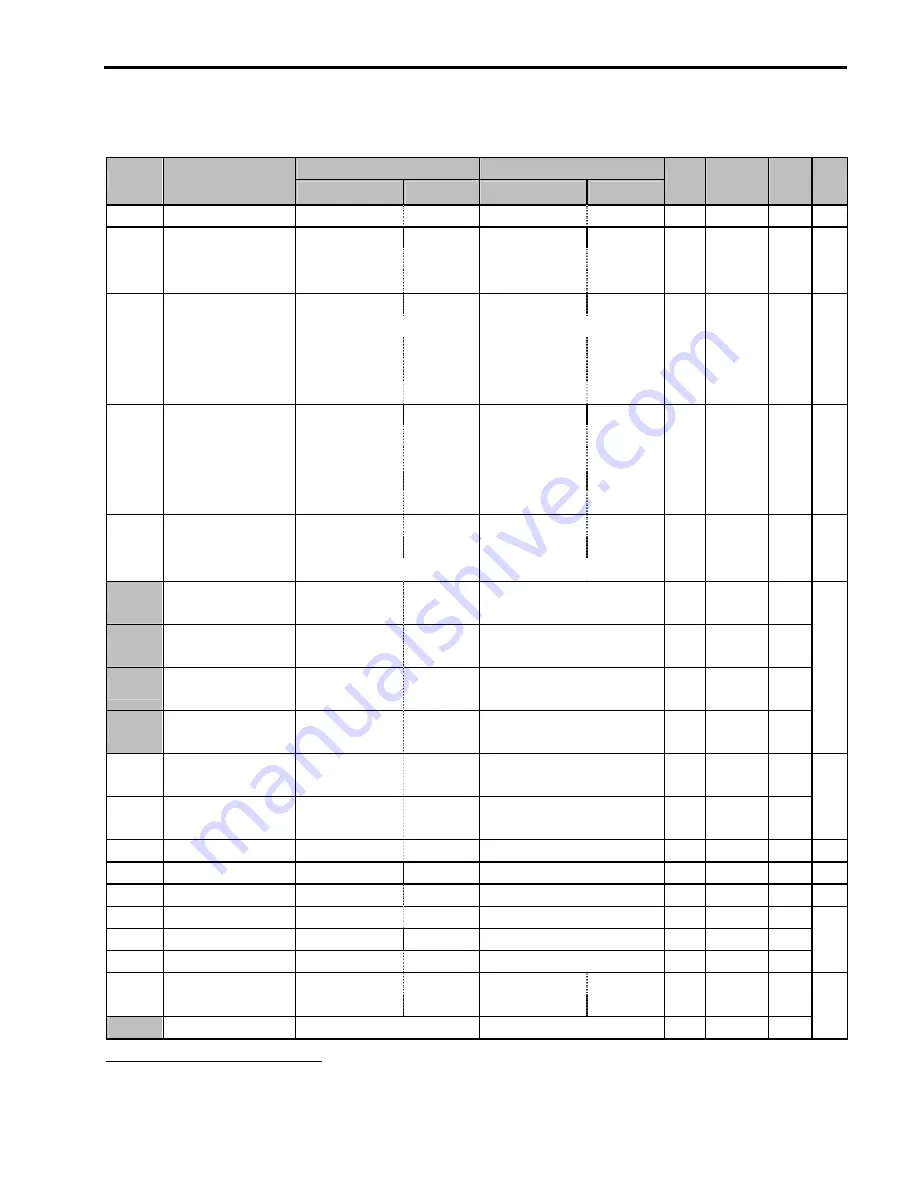
5.2 Function 1 Group [FU1]
Keypad Display
Setting Range
Code
Description
LCD
7-Segment
LCD
7-Segment
Units
Factory
Default
Adj.
During
Run
Page
FU1-00
Jump to Desired Code #
Jump code
Not displayed
1 to 60
Not available
1
1
Yes
6-2
None 0
Forward Prev
1
FU1-03
Run Prevention
Run Prev.
03
Reverse Prev
2
- None No
6-2
Linear 0
S-curve 1
U-curve 2
Minimum 3
FU1-05
Acceleration Pattern
Acc. pattern
05
Optimum 4
- Linear No
6-2
Linear 0
S-curve 1
U-curve 2
Minimum 3
FU1-06
Deceleration Pattern
Dec. pattern
06
Optimum 4
- Linear No
6-2
Decel 0
DC-brake 1
FU1-07
Stop Mode
Stop mode
07
Free-run 2
- Decel No
6-2
FU1-08
13
DC Injection Braking
Frequency
DcBr freq
08
FU1-22 to 60 [Hz]
0.01
5.00 [Hz]
No
FU1-09
DC Injection Braking
On-delay Time
DcBlk time
09
0 to 60 [sec]
0.01
0.1 [sec]
No
FU1-10
DC Injection Braking
Voltage
DcBr value
10
0 to 200 [%]
1
50 [%]
No
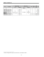
FU1-11
DC Injection Braking
Time
DcBr time
11
0 to 60 [sec]
0.1
1.0 [sec]
No
6-2
FU1-12
Starting DC Injection
Braking Voltage
DcSt value
12
0 to 200 [%]
1
50 [%]
No
FU1-13
Starting DC Injection
Braking Time
DcSt time
13
0 to 60 [sec]
0.1
0.0 [sec]
No
6-2
FU1-14
Pre-excitation Time
PreExTime
14
0 to 60 [sec]
0.1
1.0 [sec]
No
6-2
FU1-15
Hold Time
Hold Time
15
0 to 1000 [ms]
1
1000 [ms]
No
6-2
FU1-16
Pre-excitation Current
Flux Force
16
100 to 500 [%]
0.1
100.0 [%]
No
6-2
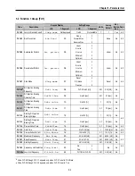
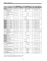
FU1-20
Maximum Frequency
Max freq
20
40 to 400 [Hz]
0.01 60.00 [Hz]
No
FU1-21
Base Frequency
Base freq
21
30 to FU1-20
0.01 60.00 [Hz]
No
FU1-22
Starting Frequency
Start freq
22
0.01 to 60 [Hz]
0.01
0.50 [Hz]
No
6-2
No 0
FU1-23
Frequency Limit selection
Freq limit
23
Yes 1
- No No
FU1-24
14
Low Limit Frequency
F-limit Lo
24
FU1-22 to FU1-25
0.01
0.50 [Hz]
No
6-2
13
Code FU1-08 through FU1-11 appears only when FU1-07 is set to ‘DC-Brake’.
14
Code FU1-24 through FU1-25 appears only when FU1-23 is set to ‘Yes’.
Summary of Contents for 30 HP30
Page 6: ......
Page 12: ......
Page 16: ...Chapter 1 Installation 1 4 BLANK ...
Page 18: ...Chapter 1 Installation 1 6 BLANK ...
Page 28: ...Chapter 1 Installation 1 16 Notes ...
Page 39: ...Chapter 2 Operation 2 11 Notes ...
Page 40: ......
Page 46: ......
Page 60: ...Chapter 4 Operation Examples 4 14 Notes ...
Page 83: ...Chapter 5 Parameter List 5 23 Notes ...
Page 84: ......
Page 92: ...Chapter 6 Parameter Description DRV 6 8 Notes ...
Page 105: ......
Page 106: ...Chapter 6 Parameter description FU1 6 14 Notes ...
Page 126: ...Chapter 6 Parameter Description FU2 6 34 Notes ...
Page 144: ...Chapter 6 Parameter Description I O 6 52 Notes ...
Page 162: ......
Page 188: ...Chapter 7 Options 7 26 Type 1 Max 400 Watt Type 2 Max 600 Watt A ...
Page 189: ...Chapter 7 Options 7 27 Type 3 ...
Page 194: ......
Page 204: ......
Page 210: ......


