


Chapter 6 - Parameter Description [DRV]
6-2
Code
Keypad Display
Parameter Name
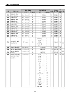
I/O-01 V1
filter
Filter Time Constant for
V1 Signal Input
I/O-02
V1 volt x1
V1 Input
Minimum Voltage
I/O-03
V1 freq y1
Frequency
Corresponding to V1
Input Minimum Voltage
I/O-04
V1 volt x2
V1 Input Maximum
Voltage
I/O-05
V1 freq y2
Frequency Corresponding
to V1 Input Maximum
Voltage
➨
Important : Increase I/O-01-[Filter Time Constant for V1
Signal Input] if the V1 signal is affected by noise causing
unstable operation. Increasing this value makes response time
slower.
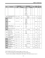
I/O-06~10 [ Analog Current Input “ I “ Signal adjustment ]
Command Freq/Torque setting via “I” input terminal
when set DRV-04 [Frequency/Torque mode] to 3 (I)
or 4 (V1+I)
Code
Default setting
Setting range
I/O-06
10 [msec]
0 ~ 10000 [msec]
I/O-07
4 [mA]
0 ~ 20 [mA]
I/O-08
0 [Hz]
0 ~ Max. freq
I/O-09
20 [mA]
0 ~ 20 [mA]
I/O-10
60 [Hz]
0 ~ Max. freq
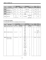
Code
Keypad display
Parameter Name
I/O-06 I
filter
Filter time constant for I signal
Input
I/O-07
I curr x1
I Input Minimum Current
I/O-08
I freq y1
Frequency Corresponding to I
Input Minimum Current
I/O-09
I curr x2
I Input Maximum Current
I/O-10
I freq y2
Frequency Corresponding to I
Input Maximum Current
➨
Important : Increase I/O-06-[Filter time constant for I signal
Input] if the I signal is affected by noise causing unstable
operation. Increasing this value makes response time slower.
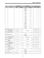
DRV-01: Acceleration Time
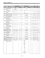
V1 analog input (0~10V)
Set freq
.
I/O-02
V1 Minimum V
I/O-03
I/O-05
I/O-04
V1 Maximum V
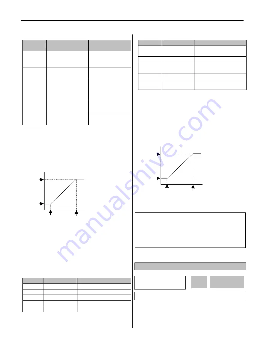
Terminal I ( 0 ~ 20 mA )
Set freq
I/O-07
I Minimum
current
I/O-08
I/O-10
I/O-09
I Maximum
current
DRV
►
Acc. time
01 10.0 sec
10.0
01
Factory Default:
10.0 sec
10.0
Related parameters : DRV-04 [Frequency or Torque Mode]
DRV-16 [Speed Unit Selection]
FU1-20 [Maximum Frequency]
FU2-39 [Control Mode Selection]
I/O-1~10 [Analog Frequency
command/Torque]
Summary of Contents for 30 HP30
Page 6: ......
Page 12: ......
Page 16: ...Chapter 1 Installation 1 4 BLANK ...
Page 18: ...Chapter 1 Installation 1 6 BLANK ...
Page 28: ...Chapter 1 Installation 1 16 Notes ...
Page 39: ...Chapter 2 Operation 2 11 Notes ...
Page 40: ......
Page 46: ......
Page 60: ...Chapter 4 Operation Examples 4 14 Notes ...
Page 83: ...Chapter 5 Parameter List 5 23 Notes ...
Page 84: ......
Page 92: ...Chapter 6 Parameter Description DRV 6 8 Notes ...
Page 105: ......
Page 106: ...Chapter 6 Parameter description FU1 6 14 Notes ...
Page 126: ...Chapter 6 Parameter Description FU2 6 34 Notes ...
Page 144: ...Chapter 6 Parameter Description I O 6 52 Notes ...
Page 162: ......
Page 188: ...Chapter 7 Options 7 26 Type 1 Max 400 Watt Type 2 Max 600 Watt A ...
Page 189: ...Chapter 7 Options 7 27 Type 3 ...
Page 194: ......
Page 204: ......
Page 210: ......


