


Chapter 6 - Parameter Description [DRV]
6-4
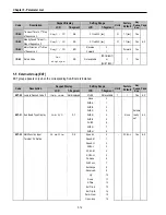
Setting Range
LCD 7-Seg
Description
Keypad
0
Run/Stop is controlled by Keypad.
Fx/Rx-1
1
Control Terminals FX, RX and 5G
control Run/Stop. (Method 1)
Fx/Rx-2
2
Control Terminals FX, RX and 5G
control Run/Stop. (Method 2)
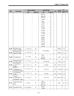
[Drive Mode: ‘Fx/Rx-1’]
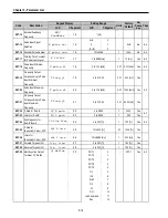
[Drive Mode: ‘Fx/Rx-2’]
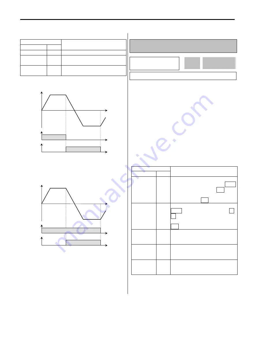
DRV-04:
Frequency or Torque Mode (Frequency /
Torque Setting Method)
* In Torque mode : LCD display: “Trque mode”
7 Segment: “04”
If the DRV-04 [Frequency or Torque Mode] is set to 2
(V1), 3 (I), 4 (V1+I), see the description of I/O-01~10
[Analog Voltage/Current input signal adjustment].
If FU2-39 is set to 4 (Sensorless_T) or 6
(Vector_TRQ), speed is displayed as the percent[%]
to the rated torque. Torque command is settable in
DRV-04 [Frequency or Torque Mode].
DRV-04 setting value is separately saved according
to which control mode (Speed or Torque) is selected
in FU2-39 [Control mode selection].
Setting Range
LCD 7-Seg
Description
Keypad-1 0
Frequency is set at DRV-00. The
frequency is changed by pressing
PROG
key and entered by pressing
ENT
key.
The inverter does not output the changed
frequency until the
ENT
key is pressed.
Keypad-2 1
Frequency is set at DRV-00. Press
PROG
key and then by pressing the
▲
,
▼
key, the inverter immediately outputs
the changed frequency. Pressing the
ENT
key saves the changed frequency.
V1 2
Input the frequency reference (0-10V) to
the “V1” control terminal. Refer to the I/O-
01 to I/O-05 for scaling the signal.
I 3
Input the frequency reference (4~20mA)
to the “I” control terminal. Refer to the
I/O-06 to I/O-10 for scaling the signal.
V1+I 4
Input the frequency reference (0~10V,
4~20mA) to the “V1”,“I” control terminals.
The ‘V1’ signal overrides the ‘I’ signal.
Output Frequency
FX-CM
Time
ON
RX-CM
ON
Forward
Reverse
Forward Run
Reverse Run
Output Frequency
FX-CM
Time
ON
RX-CM
ON
Forward
Reverse
Run/Stop
Direction
DRV
►
Freq mode*
04
Keypad-1
0
04
Factory Default:
Keypad-1
0
Summary of Contents for 30 HP30
Page 6: ......
Page 12: ......
Page 16: ...Chapter 1 Installation 1 4 BLANK ...
Page 18: ...Chapter 1 Installation 1 6 BLANK ...
Page 28: ...Chapter 1 Installation 1 16 Notes ...
Page 39: ...Chapter 2 Operation 2 11 Notes ...
Page 40: ......
Page 46: ......
Page 60: ...Chapter 4 Operation Examples 4 14 Notes ...
Page 83: ...Chapter 5 Parameter List 5 23 Notes ...
Page 84: ......
Page 92: ...Chapter 6 Parameter Description DRV 6 8 Notes ...
Page 105: ......
Page 106: ...Chapter 6 Parameter description FU1 6 14 Notes ...
Page 126: ...Chapter 6 Parameter Description FU2 6 34 Notes ...
Page 144: ...Chapter 6 Parameter Description I O 6 52 Notes ...
Page 162: ......
Page 188: ...Chapter 7 Options 7 26 Type 1 Max 400 Watt Type 2 Max 600 Watt A ...
Page 189: ...Chapter 7 Options 7 27 Type 3 ...
Page 194: ......
Page 204: ......
Page 210: ......


