background image


                                     MAN. 161 rev. 5   Use and maintenance manual Sup15               


17ª 

page of

 77


3.3.2 

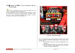
Platform control (emergency) station 


The control panel of the emergency station is placed on the right side of the 
turret and it is composed by: 


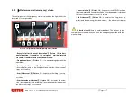
Picture  10: platform control (emergency) station 

-Key  selector  for  the  use  of  the  station  1

 (

Picture  10

)

: in hori-

zontal  position,  it  enables  the  emergency  station;  rotated 
clockwise, it enables the basket control station; 


-Proportional lever  2

 (

Picture  10

)

it is operated together with the 

operations;   

-  Pantograph  lift-descent  5


  (Picture    10

):  it  operates  the  lifting 

(lever upwards) and the lowering (lever downwards); the movement 
stops at its release. 

- Arm lift-descent  6


 (Picture  10

): it operates the lifting (lever up-

wards) and the lowering (lever downwards) ; the movement stops at 
its release. 

- Arm extension-withdrawal 3


 (Picture  10

): it activates the exten-

sion  (lever  upwards)  and  withdrawal  (lever  downwards)  movement; 
the movement stops at its release . 

- Turret rotation  4


 (Picture  10

): it operates the MEWP clockwise 

(lever upwards) and counter clockwise (lever downwards) rotation of 
the turret; the movement stops at its release . 

-  Jib  lift-descent  7


  (Picture    10

):  it  operates  the  lifting  (lever  up-

wards) and the lowering (lever downwards) ; the movement stops at 
its release .


 Under the lever 2

 there is an adjustable bolt. This bolt has to be 

completely unscrewed when you utilise the emergency operation with the 
manual pump.  


Summary of Contents for SUP15

Page 1: ...evices Point out the potential risks and or possible dangerous sit uations Provide with the necessary instructions for the ordinary maintenance operations Provide with the instructions for the filling of the check reg ister THE USE AND MAINTENANCE MANUAL IS INTEGRAL PART OF THE MACHINE In case of sale of the MEWP please give this manual to the new owner KEY FOR THE SYMBOLS USED IN THIS MANUAL CAUT...

Page 2: ...hat they will able to get on this ma chine under the guidance of an already trained staff 3 The operator shall carefully observe the safety standards foreseen by national legislations 4 The use of the machine must be entrusted only to trained and authorized staff The non observance of the aforesaid items automati cally invalidates the guarantee 0 3 Where and how to store the manual This manual or ...

Page 3: ...tary technical specifications As this manual includes both current and optional components you could find information not applicable to your equipment CMC reserves the right to update its production and its relation instruction manuals without prior notice according to the development of the tech nique to the acquisition of new experiences and or to the change of law provisions without being anywa...

Page 4: ... s Max rotation speed 0 7 m s MAX TRANSLATION SPEED 0 3 m s Max manual force allowed in the basket with 1 operator 400N Tightening torque Bolts of the bearing M16 cl 10 9 28 daNm Max load under the stabilizers 1200 daN Max specific pressure under the stabilizers 5 daN cm2 Transversal moving on slope 10 Max slope allowed surmountable in translation 25 13 Max inclination allowed by the frame 1 0 5 C...

Page 5: ...DEL S15 YEAR 2013 SERIAL NO S13A1037 TOT WEIGHT 1950 Kg CAPACITY 200 Kg INCLUDING 2 PERS MAX MANUAL FORCE ALLOWED 40 daN MAX WIND SPEED ALLOWED 12 5 m s MAX FRAME INCLINATION ALLOWED 1 EXTERNAL FEEDING 220V 50Hz C M C s r l CARATTERISTICHE S P 231 Km1 900 70026 Modugno BA ITALY Tel Fax 080 53 26 606 557 http www cmclift com E mail info cmclift com Picture 1 identification plate facsimile ...

Page 6: ...MAN 161 rev 5 Use and maintenance manual Sup15 6ª page of 77 1 3 MEWP in rest position Picture 2 Overall drawing with basket connected ...

Page 7: ...MAN 161 rev 5 Use and maintenance manual Sup15 7ª page of 77 1 4 Working diagram and stabilization area Picture 3 working diagram ...

Page 8: ...MAN 161 rev 5 Use and maintenance manual Sup15 8ª page of 77 Picture 4 stabilization area mm ...

Page 9: ... elements etc in case of par ticular heavy uses frequent use at the performance limit particular unfa vourable environmental conditions such as steel systems paper mills and so on it is better to increase the checks Anyway it is advisable to have the state of the machine checked by the manufacturer factory or by an authorized assistance point at least every 1500 2000 working hours or once a year 1...

Page 10: ...ined access position and that it is made of at least one work platform with controls an extendible structure and a frame It is forbidden to access or to get off the work platform at different levels 2 2 Machine purpose The aerial work platform Sup15 is an equipment which enables the opera tors to reach the working place when this is high positioned The machine has been designed for an essentially ...

Page 11: ...MAN 161 rev 5 Use and maintenance manual Sup15 11ª page of 77 2 3 Description of the main components 5 8 6 Picture 5 MEWP main components ...

Page 12: ...turret rod side and to the pantograph upper crank stem side and it has a double effect balancing valve This cylinder is hinged to the turret 2 3 4 Telescopic arm 8 Picture 5 The telescopic arm is hinged to the turret 8 Picture 5 The telescopic arm is composed by two elements 1 fixed arm hinged to the pantograph con necting rod and 1 sliding arm The sliding or re entry movement of the telescopic ar...

Page 13: ...e lever forward the stabilizer lowers Pushing the lever backwards the stabilizer withdraws left front stabilizer lever3 Picture 6 pushing the lever forward the stabilizer lowers pushing the lever backwards the stabilizer withdraws left rear stabilizer lever4 Picture 6 pushing the lever forward the stabilizer lowers pushing the lever backwards the stabilizer withdraws OPTIONAL on the hard right of ...

Page 14: ...icates the consent to the travel operations Emergency mushroom shaped button 8 Picture 7 blocks the machine unfeeding the control circuits being mechanically self holding to reset the machine function it is necessary to unlock it rotating it CW this switch has the priority on any other control it is only possible to use the emergency lowering to the ground Picture 8 left and right side of the wire...

Page 15: ...cond emergency placed on the turret Picture 10 Through connecting the emergency station opening padlock and door emergency station protection the exercise station controls are disabled 3 3 1 Platform control exercise position Picture 9 Platform control exercise position The platform control exercise station Picture 9 is located inside the bas ket and it is formed by 1 2 3 4 5 6 7 8 9 10 11 12 ...

Page 16: ...switch levelling operation consent 5 Picture 9 for the levelling operation it is necessary to push this button together with the lever 6 Picture 9 Joystick lever for jib lifting control basket levelling 6 Picture 9 it carries out the aforementioned operations pushed together with the dead man switch 5 Picture 9 it carries out the levelling Perform the basket levelling operation only when the MEWP ...

Page 17: ...wnwards the movement stops at its release Arm lift descent 6 Picture 10 it operates the lifting lever up wards and the lowering lever downwards the movement stops at its release Arm extension withdrawal 3 Picture 10 it activates the exten sion lever upwards and withdrawal lever downwards movement the movement stops at its release Turret rotation 4 Picture 10 it operates the MEWP clockwise lever up...

Page 18: ... Do not operate when the wind speed exceeds a 12 5 m s 45 Km h We hereby enclose Schedule 1 Beaufort wind scale Table 1 Beaufort wind scale Table 1 Beaufort wind scale Wind power Wind speed Land conditions Beaufort number description m s Km h 0 Calm 0 0 2 1 Calm Smoke rises vertically 1 Light air 0 3 1 5 1 5 Wind motion visible in smoke 2 Light breeze 1 6 3 3 6 11 Wind felt on exposed skin Leaves ...

Page 19: ... Minimum approach dis tance 300 V and less Avoid Contact Over 300 V not over 750 V 1 ft 0 in 30 5cm Over 750 V not over 2 kV 1 ft 6 in 46 cm Over 2 kV not over 15 kV 2 ft 0 in 61 cm Over 15 kV not over 37 kV 3 ft 0 in 91 cm Over 37 kV not over 87 5 kV 3 ft 6 in 107 cm Over 87 5 kV not over 121 kV 4 ft 0 in 122 cm Over 121 kV not over 140 kV 4 ft 6 in 137 cm ...

Page 20: ...nce of persons in proximity during the operations is for bidden Alternatively the load unload can be done through ramp exploiting the mo tricity of the machine as well as its ability to overcome slopes not 25 13 If you choose this option please proceed with the following proce dure and carefully reading the danger notes suggested Comply with the rules in force relevant to the width height weight a...

Page 21: ...MAN 161 rev 5 Use and maintenance manual Sup15 21ª page of 77 Picture 12 basket joint pin and splint pin ...

Page 22: ...on par 3 2 Picture 7 provided that the cabled remote control is cor rectly fastened to its connection Picture 14 electrical connection of the cabled remote control 2 Check that no one is in proximity 3 Place the couple of ramps of adequate dimensions and bring in correspondence of the machine tracks 4 Check that the ramps slope does not exceed 25 and that those are perfectly clean from grease mud ...

Page 23: ...ual Sup15 23ª page of 77 If you have to climb the basket has to be positioned at the back Picture 15 translation direction upward If you have to descend the basket has to be positioned at the front Picture 16 translation direction downward ...

Page 24: ... mode and all movements are blocked To reset the normal working conditions hold the microswitch for the arm positioning or turret centering pressed down and take the ma chine back to its rest condition WARNING Should the machine get on a truck use loading ramps with suitable dimensions and strength Secure the machine to the truck plane by the junctions on the base cart Make sure the machine is tur...

Page 25: ... want to use the electrical engine Connect the 220 V electrical socket P Picture 19 to the nearest electrical source 110 V in England Set the I switch on ON Picture 19 Start the engine pushing the start button 1 Picture 9 par 3 3 1 Picture 19 Control board for the electrical starting 3 The machine is ready for translation or to be stabilized 4 Identify the area work station area which is nearest t...

Page 26: ... cated on the same and that in the contact point of eve ry stabilizer plate with the ground there are no man holes floors or other soft structures If such conditions are not met it is strictly for bidden to use the MEWP 6 Place the MEWP on the selected area 7 Define the work station area with appropriate signage white red ribbon white red chains cones etc During the translation operations respect ...

Page 27: ...icle by comparing the air bubble on the counter frame the maximum frame slope allowed is 1 one degree Once the stabilization is over lights 3 Picture 24 and 4 Picture 9 respectively indicating stabiliza tion and consent to the operation of the platform aerial part At the same time the two lights 3 and 4 Picture 9 par 3 3 1 will turn on respectively indicating platform use consent and balance Carry...

Page 28: ...t the light 4 par 3 3 1 Picture 9 will turn off First lift the pantograph in order to rise from the support It is therefore strictly forbidden to rotate the turret as first movement since it could cause heavy damages to the carpentry 4 4 6 Positioning of the MEWP in the transport posi tion 17 To place the work platform in the transport position it is necessary to first operate the MEWP aerial part...

Page 29: ...MEWP aerial part can be operat ed by the ground operator by using the Platform controls emergency sta tion described in par 3 3 2 This station can be operated by turning in verti cal position the key clockwise 1 Picture 23 Picture 23 emergency station closing carter 4 5 3 Hand pump hydraulic system failure In case of emergency fuel exhaustion etc to get the pressure inside the hydraulic circuit ne...

Page 30: ...tions can be also carried out by enabling the Platform control emergency station described in paragraph 3 2 2 In case of emergency first withdraw the telescopic arm and then lower telescopic arm and Jib After repositioning the platform in rest position fasten the handle 2 Picture 24 and start destabilizing the MEWP While the ground operator activates the pump after inserting the supplied lever the...

Page 31: ...latform compo nents you can use the hand pump 1 Picture 24 on the right of the turret distributor as an alternative to the thermal engine Picture 26 electro valves group First close the platform unscrewing the hydraulic tap knob near the tank 2 Picture 24 and start the MEWP closing operations chronologically follow ing these steps Ground operator activates the pump after engaging the sup plied lev...

Page 32: ...hile the ground op erator activates the pump after engaging the supplied lever the other op erator will carry out destabilization first performing in chronological order these steps another operator first removes the lead seal from the golden lock ring then the ring then screws the right exchange electro valve cursor 1D Picture 26 then unscrew the knob on the exchange electrovalve 2D then go to th...

Page 33: ...ted in Maintenance chapter cap 8 Check that the safety device are working and efficient Some of the platform components integrated groups for the stabilizers max pressure valve on the turret which are important for the safety of the MEWP are calibrated in CMC s r l factory and the containers are sealed before the delivery of the MEWP to the customer It is strictly forbidden to tamper with these co...

Page 34: ...WP In any dangerous or irregular conditions stop the machine by using the emergency button Before starting the machine again check that the dangerous conditions are over It is strictly forbidden to level the basket when the machine is in working position Do not operate when the MEWP is in failure It is forbidden to use the platform control emergency position when there are operators inside the bas...

Page 35: ... buildings etc and moving vehicles cranes etc objects with the truck cabin with the stabilizers and with other structure parts It is forbidden to use ladders or tables on the basket in order to increase the MEWP s outreach or working height Be careful when working in close buildings due to the wind tunnel effect sudden blasts could cause swinging thus impairing the machine stability It is forbidde...

Page 36: ...ator Charge limiting device OPTIONAL B Hydraulic devices Max pressure valves Block valve and parachute valve mounted on the lifting cylinders Manual pump for the emergency operations Oil flow adjuster for the control of the descent speed C Mechanical devices Hydraulically controlled negative disc brakes 1 10 m height border guardrail on the basket Basket access self locking bar Basket with safety ...

Page 37: ... the machine there are the following marks Before using the MEWP it is compulsory to check the presence and the perfect readability of these marks In case of absence or de cay of the marks contact the Servicing Picture 27 identification plate example Picture 28 working diagram ...

Page 38: ...MAN 161 rev 5 Use and maintenance manual Sup15 38ª page of 77 Picture 29 stabilizers controls Picture 30 platform controls basket work station ...

Page 39: ...MAN 161 rev 5 Use and maintenance manual Sup15 39ª page of 77 Picture 31 platform control emergency position Picture 32 emergency turnout Picture 33 parking operations box ...

Page 40: ...MAN 161 rev 5 Use and maintenance manual Sup15 40ª page of 77 Picture 34 main box Picture 35 selector for translation stabilization Picture 36 parking dead man button Picture 37 ...

Page 41: ...MAN 161 rev 5 Use and maintenance manual Sup15 41ª page of 77 Picture 38 Picture 39 Over 27 97 mph wind force grade 6 stop using the lifting machine immedi ately Picture 40 Picture 41 ...

Page 42: ...icture 42 right translation direction PORTATA MASSIMA MAX CAPACITY CAPACITE MAXIMALE MAX TRAGFAEHIGKEIT CAPACIDAD MAXIMA MAX BELASTING 80Kg 80Kg 40Kg 200 Kg Picture 43 max capacity allowed in the basket IT IS FORBIDDEN TO STAY IN THE ACTION RAY OF THE PLATFORM IN MOVEMENT Picture 44 do not stay in the MEWP working area IT IS FORBIDDEN TO RAISE THE CHARGE ON THE BASKET AND TRANSFER PEOPLE WITH THE ...

Page 43: ...indicates the position of the emergency manual pump LEV EL TH E M A CH I N E BEFO RE STA RTI N G I T Picture 47 level the frame S A F E T Y B E LT L I N K A G E Picture 48 indicates the position of the safety belts fastening rings Picture 49 shearing and cutting hazard Picture 50 shearing and cutting hazard ...

Page 44: ...5 44ª page of 77 Picture 51 instability hazard in case of soft ground Picture 52 warning signs on the machine Kg WIND 27 96 mph T 131 F T 13 F Picture 53 prohibition signs on the machine Picture 54 max load and specific pressure on the stabilizers ...

Page 45: ...MAN 161 rev 5 Use and maintenance manual Sup15 45ª page of 77 Figure 55 aerial work platform use guidelines Figure 56 adhesive arrows on frame ...

Page 46: ... the functioning of the truck electrical system affect the platform s functioning thus impairing its normal performances Periodically check the efficiency of the electric plant batteries alternator charge alternator regulator All operations requiring the intervention on the machine com ponents are to be performed by authorized and trained technical staff Non authorized staff shall not replace any ...

Page 47: ...the operations requiring the intervention on the compo nents of the machine shall be carried out by authorized and trained technical staff Non authorized staff shall not replace any of the components Many components have been calibrated a correct calibration of these parts possible only in CMC or in authorized workshops is necessary to ensure the safety of the machine ...

Page 48: ...ps Use only CMC original spare parts even if on the market there are equiva lent or similar parts The frequency of the maintenances is indicated in the relevant table By this frequency we mean a normal use of the equipment while for particular ly rough uses or in harmful environments presence of dust sand etc an optional frequency is left to the good sense of the user A correct use of the platform...

Page 49: ...ions by using the emergency con trols placed on the turret when no one is aboard Lifting and lowering of the tel escopic arm Lifting and lowering of the jib Clockwise and anticlockwise rotation of the turret Extension and withdrawal of the telescopic arm During the test operations check that the basket floors keeps a horizontal position Check the functioning of the stabilizers block valves keeping...

Page 50: ...graph Trou ble shooting per form the opera tions indicated in the said para graph USER If the prob lem is not solva ble following the instructions indi cated in the para graph Trouble shooting it is strictly forbidden to use the MEWP Contact the Ser vicing CMC Operations by USER In case of nega tive result of the checks settlement by Check the absence of splits cracks rust on the structure of the ...

Page 51: ...e flexible pipes of the pipe fitting and the components of the hydraulic circuit check that there are no oil leakage in hydraulic circuit Replacement USER CMC Check that the electrical contacts are not slacken Reset connec tions USER CMC Check that there are no trace of clashes on the equipment It is strictly forbidden to use the MEWP Con tact the Servicing CMC ...

Page 52: ...nd auxiliary motor air filter USER CMC Check the cleanliness of the hydraulic filters USER CMC Check the right positioning and integrity of the stickers USER CMC Check that there are no consumption signals and or corro sion signal on the paint of the hydraulic couplings USER CMC 8 3 Monthly maintenance or every 120 hours Operations by Greasing of pins and movable parts USER CMC Washing of the equi...

Page 53: ...aintenance or every 300 hours Operations by Check the tightening of the bolts of the bearing the geared motor and the frame USER CMC 8 5 Maintenance after the first 400 hours Operations by Replacement of the hydraulic filters USER CMC Registration of the movement of the arms CMC ...

Page 54: ... the replacement of the hydraulic oil follow these instructions 1 Place the machine in transport position with the oil at working tem perature to do that operate some manoeuvre before going on with the above described operations 2 Suck in the oil from the tank 3 Dismantle the hydraulic filter 4 Replace the filter 5 Fill the tank letting the oil pass through a filter with 25 micron filtra tion N B ...

Page 55: ... Biennial maintenance Operations by Complete check of the whole machine and note the results in the appropriate manual section CMC 8 9 Five yearly maintenance Operations by Complete check of the whole machine and note the results in the appropriate manual section CMC ...

Page 56: ... area assigned for the maintenance operations by suited enclosure or by a red white band ribbon and do not allow entrance to unauthorized staff Do not modify or remove safety devices Do not modify calibrated pieces During the washing operation do not lead the water jet directly on the electrical panels of the MEWP and do not use cleansing ag gressive chemicals dangerous for the components of the M...

Page 57: ...210 3045 Bar psi Outrigger functions 190 2755 bar psi Chain drive 220 3190 bar psi 8 13 Maintenance consumables hydraulic tank capacity 21 litres Grease For arm extension and stabilizers WHITE STAR NLGI 0 AND 2 for lubricators and bearing MOLYTEX EP 2 for lubricators and bearing GEARTEX EP A 80W 90 for lubricators and bearing Before oil replacement place the oil drip tray in order to avoid the lea...

Page 58: ...lenoid valves and similar Oils and lubricants hydraulic oil reducer lubricants and lubricants greases 8 15 Servicing For repairs and service of your platform refer only to Servicing CMC s r l S P 231 km 1 900 70026 Modugno BA Italy Phone 39 080 5326606 Fax 39 080 5368541 info cmclift com www cmclift com PLEASE NOTICE FOR ANY COMMUNICATION PROVIDE WITH THE TYPE OF THE MACHINE AND ITS SERIAL NUMBER ...

Page 59: ...work Remedies 1 Replace hydraulic pump If the problem persists contact the servicing Problem WITH THE STABILIZED MEWP THE GREEN LIGHT DOES NOT TURN ON Cause 1 The green light does not work 2 Micro switch system does not work 3 Stabilization is insufficient Remedies 1 Replace micro switch 2 Further extract stabilizers If the problem persists contact the servicing ___________________________________...

Page 60: ... devices par 10 7 Considerable failures and relevant repairs par 10 8 Periodical checks and maintenance journal par 10 9 Notes par 10 10 10 1 Delivery of the MEWP to the first owner brand CMC model S15 serial number manufacture year 2013 ha sbeen delevered by CMC s r l date CMC s r l 02 07 13 according to the contractual conditions established with the technical dimensional and functional features...

Page 61: ...eginning and that further changes have been written on this register The seller The buyer ___________________________________________________________ On the the ownership of the MEWP in subject is transferred to the firm company It is certified that on the above date the functional dimensional and tech nical features of the MEWP in subject are in keeping with those foreseen at the beginning and th...

Page 62: ...vided by Cause of the replacement Place Date Stamp and signature of the responsible for the firm in charge The user ___________________________________________________________ Description of the component Manufacturer Provided by Cause of the replacement Place Date Stamp and signature of the responsible for the firm in charge The user _________________________________________________________ Descr...

Page 63: ... of the component Manufacturer Provided by Cause of the replacement Place Date Stamp and signature of the responsible for the firm in charge The user Description of the component Manufacturer Provided by Cause of the replacement Place Date Stamp and signature of the responsible for the firm in charge The user ___________________________________________________________ Description of the component ...

Page 64: ...on of the component Manufacturer Provided by Cause of the replacement Place Date Stamp and signature of the responsible for the firm in charge The user Description of the component Manufacturer Provided by Cause of the replacement Place Date Stamp and signature of the responsible for the firm in charge The user __________________________________________________________ Description of the component...

Page 65: ...ion of the component Manufacturer Provided by Cause of the replacement Place Date Stamp and signature of the responsible for the firm in charge The user Description of the component Manufacturer Provided by Cause of the replacement Place Date Stamp and signature of the responsible for the firm in charge The user __________________________________________________________ Description of the componen...

Page 66: ...of the component Manufacturer Provided by Cause of the replacement Place Date Stamp and signature of the responsible for the firm in charge The user Description of the component Manufacturer Provided by Cause of the replacement Place Date Stamp and signature of the responsible for the firm in charge The user __________________________________________________________ Description of the component Ma...

Page 67: ...s and relevant repairs Description of the failure Cause Repairs performed Place Date Stamp and signature of the responsible for the firm in charge The user Description of the failure Cause Repairs performed Place Date Stamp and signature of the responsible for the firm in charge The user ...

Page 68: ...up15 68ª page of 77 10 9 Periodical checks and maintenance journal The user shall observe the maintenance and control program described in this manual DATE DESCRIPTION OF THE INTERVENTION SIGNATURE DATE DESCRIPTION OF THE INTERVENTION SIGNATURE ...

Page 69: ...MAN 161 rev 5 Use and maintenance manual Sup15 69ª page of 77 DATE DESCRIPTION OF THE INTERVENTION SIGNATURE DATE DESCRIPTION OF THE INTERVENTION SIGNATURE ...

Page 70: ...MAN 161 rev 5 Use and maintenance manual Sup15 70ª page of 77 10 10 Notes ...

Page 71: ...MAN 161 rev 5 Use and maintenance manual Sup15 71ª page of 77 10 11 Maintenance of tracked undercarria ges ...

Page 72: ...MAN 161 rev 5 Use and maintenance manual Sup15 72ª page of 77 ...

Page 73: ...MAN 161 rev 5 Use and maintenance manual Sup15 73ª page of 77 ...

Page 74: ...MAN 161 rev 5 Use and maintenance manual Sup15 74ª page of 77 ...

Page 75: ...MAN 161 rev 5 Use and maintenance manual Sup15 75ª page of 77 ...

Page 76: ...MAN 161 rev 5 Use and maintenance manual Sup15 76ª page of 77 ...

Page 77: ...rgency operations 29 4 6 Safety rules 33 4 7 Safety devices 36 5 Markings 37 6 Electrical system 46 7 Hydraulic system 47 8 Maintenance 48 8 1 Daily maintenance 49 8 2 Weekly maintenance or every 40 hours 52 8 3 Monthly maintenance or every 120 hours 52 8 4 Quarterly maintenance or every 300 hours 53 8 5 Maintenance after the first 400 hours 53 8 6 Six monthly maintenance or every 750 hours 54 8 7...

Reviews: