


Evaluation Kit for CMX979 (engineering samples)
EV9790
2017 CML Microsystems Plc
25
UM9790/1
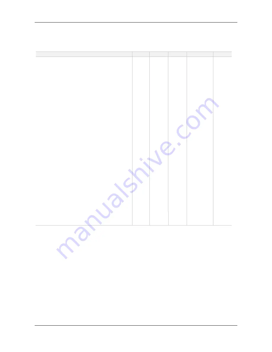
8.1.3
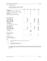
Operating Characteristics
For the following conditions unless otherwise specified:
Xtal Frequency = 19.2MHz, V
IN
= 6.0V, T
AMB
= +25°C.
Notes
Min.
Typ.
Max.
Units
DC Parameters
IIN (Regulators and reference on, CMX979 in reset)
1
–
6.5
–
mA
IIN (CMX979 RF PLL and VCO enabled, LO OUT enabled,
divide by 1 )
1
–
45
–
mA
IIN (IF PLL enabled, divide by 1 output)
1
–
16
–
mA
IIN (CMX979 IF and RF PLLs and VCOs enabled)
1
–
52
–
mA
RF PLL / VCO Parameters
Frequency Range
2700
–
3600
MHz
Divide by 2 Output Range
1350
1800
MHz
Divide by 4 Output Range
675
900
MHz
Divide by 6 Output Range
450
600
MHz
Divide by 8 Output Range
337.5
450
MHz
RF output, J1
2,3
–
-7
–
dBm
Output Impedance
–
50
–
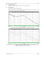
Phase Noise (typical) at MHz, 10kHz offset
–
TBD
–
dBc/Hz
IF PLL / VCO Parameters
Frequency Range
4
700
900
1000
MHz
Divide by 4 Output Range
175
250
MHz
Divide by 8 Output Range
87.5
125
MHz
Divide by 16 Output Range
43.75
62.5
MHz
RF output, J6
2,3
–
-10
–
dBm
Output Impedance
–
High8k
// 0.6pF
–
Reference input (Ext Clk)
Input Impedance
–
High
–
Sensitivity
5
–
-20
–
dBm
Microcontroller Interface
For timings see CMX979 Datasheet
Notes:
1.
PCB current consumption, not current consumption of the CML devices.
2.
Unmatched
3.
4.
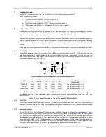
Using the default value of inductor L3 (8.2nH).
5.
Measured at J3 from a 50 Ω source.
6.
This is Advance Information; changes and additions may be made to this document. Parameters marked TBD or left blank
will be included in later issues of this document. Information in this advance document should not be relied upon for final
product design.


