


Evaluation Kit for CMX979 (engineering samples)
EV9790
2017 CML Microsystems Plc
6
UM9790/1
5
Quick Start
This section provides instructions for users who wish to experiment immediately with this Evaluation Kit. A more
complete description of the kit and its uses appears later in this document. The user should also read the appropriate
CMX979 datasheet before using the EV9790 board.
NOTES: The default configuration of EV9790 uses the following configuration:
U4: 19.2MHz frequency reference without buffer.
5.1
Setting-Up
The following procedure is recommended:
1.
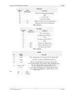
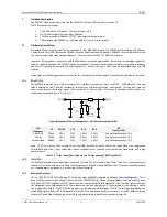
Connect the boards as shown in Figure 5. Note that the HB0003 Interface Board (supplied) needs to be connected
between the PE0003 and EV9790 boards.
2.
Ensure that the power supply and reference oscillator selection links are correctly configured.
3.
LO Output signals from the RFPLL can be monitored by a spectrum analyser connected to J1.
4.
Output from the IF VCO /PLL can be monitored by a spectrum analyser connected to J6 (IF VCO Out).
5.
Apply power to the boards.
The boards are now ready for operation.
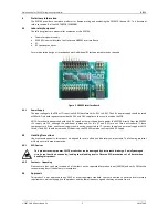
Figure 4 HB003 connected to an EV9790
-
-
-
J3
J6
EV9790
J11
PE0003
USB
Connection
to PC
C
-B
U
S
J3 (or J7)
J5
J7
+5V
GND
J1
+ 6V
GND
Spectrum
Analyser
HB0003
Figure 5 Typical Evaluation Connections for EV9790


