Page 7
Safety hose open systems (open expansion)
•
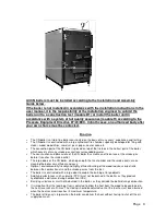
All the system boilers must have a connection to the atmosphere through a safety hose which cannot
be blocked.
•
Safety hoses must depart from the top of the system boiler(s). They must run at an uphill gradient to
the open expansion vessel and from there run at a steady downhill gradient, at a suitable distance
from a drain and in such a way that the outlet of hot water does not result in a risk of injury. The outlet
point must be cut at an angle.
•
At the highest point of the safety hose there must be an internal diameter of minimum 15 mm as a
siphon break.
•
The vertical distance from the highest point of the system to the boiler must not exceed 10 meters.
•
The total length of the safety hose must not exceed 20 meters.
•
For boilers > 60 kW the safety hose must have a minimum internal diameter of 35.5 mm
•
All pipes must be approved for 120 °C and minimum 10 bar over pressure.
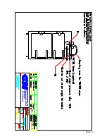
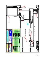
For installation with operational pressure >0.5 bar and open expansion principle diagram pages
17 & 20 must be used
•
If the operational pressure of the boiler exceeds 0.5 bar over pressure, the boiler unit (the installed
boiler including fittings and safety equipment) is covered by the Pressure Equipment Directive
97/23/EEC ”Installation of pressurised equipment”, which requires that the boiler unit must fulfil
certain essential safety requirements regarding the safety equipment of the boiler etc.
The boiler
must be fitted with a cooling spiral
•
Expansion vessel
: The vessel must be installed in accordance with the directions of The Health and
Safety at Work Act 1974.
•
The bottom of the expansion vessel should be installed only above pipes/radiator of the central
heating system and with an open expansion vessel. Block valves must under no circumstances be
placed between the boiler and the expansion vessel.
There must under no circumstances be any
circulation in the expansion vessel.
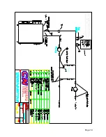
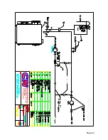
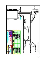
The boiler must be installed with pos. nos. 1, 2, 3, 4, 5, 7, 9, 10, 13 (drawings pages 17 & 20)
Description
Type / Requirements
Draw. Pos no. Supplier
Shunt valve
TA type TRV 300
1
CN (supplied)
Oper. thermostat
BC components type NTC-2322
2
CN (supplied with stoker)
Overheat. thermostat
Honeywell type L6188
3
CN (supplied with stoker)
Boiler thermometer
0-120 degrees
4
Installation engineer
Pressure gauge
(manometer)
0-3 maximum 5 bar, red mark at 2.5 bar
4
Installation engineer
Expansion vessel
CE labeled, minimum 8 % of total system
water volume
5
Installation engineer
Safety valve
CE approved
2 pces., 2.5 bar, clearance minimum 20 mm
7
Installation engineer
Cooling spiral
CN80:
Wieland heat exchanger type WRK 13
9
CN (supplied)
Cooling spiral
CN120:
Wieland heat exchanger type WRK 13
9
Safety thermostat
Honeywell type TS130, CE approved
10
CN
Water shortage protection RT 200 Pressostat
13
Installation engineer
Summary of Contents for 120
Page 17: ...Page 17 ...


