Page 9
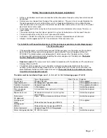
110
5,2
120
6,0
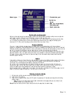
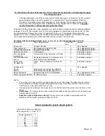
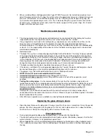
Expansion vessel efficiency
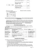
Example of calculation (new systems)
in % after initial and operational pressure
Oper. pressure bar
In.
pres.
1.0
1.5
2.0
2.5
0.5
25
40
50
57
1.0
20
33
42
1.5
16
28
2.0
14
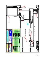
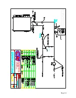
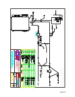
For boilers with open expansion and operational pressure < 0.5 bar, the principle diagram pages 18 &
21 must be used
If the operational pressure of the boiler is below 0.5 bar, the boiler must be installed in accordance with
the directions of The Health and Safety at Work Act 1974 about combustion hot water systems.
Cooling
spiral is not required
.
The bottom of the expansion vessel should be installed above the highest
pipe/radiator of the central heating system and with an open expansion vessel. Block valves must under
no circumstances be placed between the boiler and the expansion vessel.
There must under no
circumstances be any circulation in the expansion vessel.
Size of expansion vessel open system:
The expansion vessel must be at least 8 % of water content ( rese pipes and radiators)
acc. to Btv32.
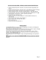
Boilers exclusively used for manual stoking must be installed with following pos. nos. 1, 4, 5, 11, 12
(draw. page 18)
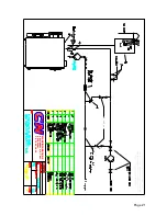
Boilers used with stoker pos. nos. 1, 2, 3, 4, 5 (draw. page 21)
Description
Type / Requirements
Draw. Pos no. Supplier
Expansion vessel
CE labeled, minimum 8 % of total system
water volume
5
Installation engineer
Oper. thermostat
BS components type 2322
2
CN (supplied with stoker)
Overheat. thermostat
Honeywell type L6188
3
CN (supplied with stoker)
Boiler thermometer
0-120 C° degrees
4
Installation engineer
Pressure gauge
(manometer)
0-3 maximum 5 bar, red mark at 2.5 bar
4
Installation engineer
Accumulation tank
Type approved in acc. with ”Declaration on
Installation of Pressurised Equipment”
11
Installation engineer
Shunt valve
TA type TRV 300
1
CN (supplied)
Flue regulator
1” Robust
12
Installation engineer
Testing the safety equipment
.
The engineer must test the safety equipment before the unit is handed over to the user.
•
The engineer must check that the operation thermostat is working.
•
The engineer must also check the overheating protection.
This is done by removing the overheating thermostat from the dip pipe and placing it in boiling water.
The thermostat should now cut out and the system stop. Reset the thermostat once the temperature
has fallen, and place it back in the dip pipe.
•
The engineer must also check that the safety valves open at max 2.5 bar.
•
The engineer must test the operation of the thermal valve for the cooling spiral. The valve should
open at a sensor temperature of maximum 95 °C. Remove the sensor from the dip pipe and place it
in boiling water. Check that water now flows through the cooling spiral. Replace the sensor in the dip
pipe.
Maximum system temperature °C
90 °C
Water content heating system
Boiler (type 25) 180 L.
Installation 350 L.
530 L.
Water exp. (530x3,6/100)
19.08
Expansion vessel efficiency
57 %
Size expansion vessel
(19.08x100/57)=33.47=
34 L.
Summary of Contents for 120
Page 17: ...Page 17 ...


