background image

X

X

N

N

E

E

T

T


N

N

e

e

t

t

w

w

o

o

r

r

k

k


V

V

a

a

n

n

d

d

a

a

l

l


D

D

o

o

m

m

e

e


C

C

a

a

m

m

e

e

r

r

a

a


I

I

n

n

s

s

t

t

a

a

l

l

l

l

a

a

t

t

i

i

o

o

n

n


M

M

a

a

n

n

u

u

a

a

l

l


5 /

 20 

2. About the Product 

2

2

.

.

1

1

.

.


C

C

o

o

n

n

t

t

e

e

n

n

t

t

s

s


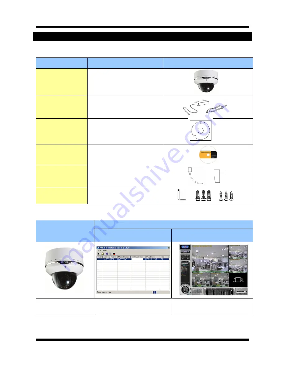
Please make sure the following contents are included when you open the package

Contents 

Description 

Additional info. 

XNET 

XNET IP Vandal Dome Camera   


POWER ADAPTOR 

AC Power Cable 

INPUT : 100~240VAC 50-60Hz 
OUTPUT : 12VDC 2A    AC24V 2.5A 
2Jack Cable 


GUIDE PATTERN 

Guide Pattern 


CD   

Software and User’s manual   


DC JACK 

DC CONNECTOR 

Connect the Power Adaptor DC jack 

Connect the DC jack Connector 


Accessory  

  SCREW 3EA, Wall Anchors 3EA 

L (wrench) 1EA 


2

2

.

.

2

2

.

.


P

P

r

r

o

o

d

d

u

u

c

c

t

t


I

I

n

n

f

f

o

o

r

r

m

m

a

a

t

t

i

i

o

o

n

n


XNET 

(

IVP5035VR

Install CD 

IP-Installer 

Viewer Program   

(CNB-CMS) 


IP Vandal Dome Camera 

(IVP5035VR) 

A software that assigns an IP address 
to the product     

A software that monitors and records 
Audio and Video signal from the device 

Summary of Contents for IVP5035VR

Page 1: ...Ver 1 0 XNET Network Vandal Dome Camera IVP5035VR Installation Manual...

Page 2: ...urer immediately if you think there is any problem with the product Contact the store or the manufacturer before disassembling the product for alteration or repair XNET is a trademark of CNB Technolog...

Page 3: ...ents 5 2 2 Product Information 5 2 3 Hardware Designation 6 2 3 1 Switch and Controls 6 2 3 2 Connecting Cables 7 2 3 3 Connecting to Alarm Devices 9 3 Software Installation 10 3 1 Installing XNET 10...

Page 4: ...PEG and sent to meet various applications of network or user 2 way Audio Communication Bi directional voice communication between Client s PC and XNET Smart Event feature On the top of motion detectio...

Page 5: ...R AC Power Cable INPUT 100 240VAC 50 60Hz OUTPUT 12VDC 2A AC24V 2 5A 2Jack Cable GUIDE PATTERN Guide Pattern CD Software and User s manual DC JACK DC CONNECTOR Connect the Power Adaptor DC jack Connec...

Page 6: ...ned on SYSTEM LED The system operates normally when the Green LED blinks LINK LED Red light indicates that the network is properly connected ACT LED Green light indicates that the XNET system connecte...

Page 7: ...power supply provided in the package Except when connected to AC24V DC jack please use DC12V 2A AC24V 2 5A Analog Video Output Use this output for immediate monitoring of the video during installatio...

Page 8: ...on to Alarm Devices for detailed instruction on how to connect sensors and Relays Do not use this connector when powering up the product through LAN cable PoE The product is not covered under warranty...

Page 9: ...Wires from various sensor type IR heat and magnetic can be connected to Alarm in terminal as shown in figure 2 5 NC or NO of sensor input can be selected at Menu screen Alarm Sensor device requires a...

Page 10: ...plained in this section or if the product is not functioning as described please refer to FAQ before contacting the store Our homepage is http www cnbtec com 3 3 1 1 I In ns st ta al ll li in ng g X X...

Page 11: ...automatically set to the default value 192 168 123 100 after connecting XNET camera to your PC directly This process approximately takes 20 30 seconds 2 Please follow the direction to modify PC s netw...

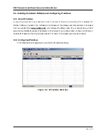
Page 12: ...la at ti io on n M Ma an nu ua al l 12 20 3 Please insert the Setup CD into your CD ROM drive and then please setup IPInstaller program 4 Please click Next button when the Setup screen appear 5 Please...

Page 13: ...n nu ua al l 13 20 7 XNET IP Installer program is automatically launched like below right after the program installation Please double click XNET camera on the list 8 XNET camera is successfully conne...

Page 14: ...User name and Password XNET camera s Default User name and Password User name root Password admin Connect XNET with a router Please connect XNET camera and PC to a router using LAN cables like below N...

Page 15: ...ct IP camera and monitoring PC to a network IP Installer software provided in the Installation CD included in the package and also available to download from our website http www cnbtec com will confi...

Page 16: ...era of which you wish to change the IP address and click Set IP Address button to bring up the following box in Figure 3 3 Figure 3 3 IP Address box 3 When you enter the IP address and click Set butto...

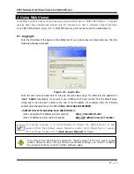
Page 17: ...page The default id and password is root admin respectively If you want to use a different HTTP port number from the default value simply put a colon and port number at the end of the IP address For...

Page 18: ...d saves the current image as a still picture The image is saved as jpeg file in the following folder C xNetCapture Setting Brings up Menu screen Setup page for each XNET feature can be opened from thi...

Page 19: ...A 1280 x 1024 720P 1280x720 D1 720 x 480 720 x 576 VGA 640x480 CIF 352 x 240 352 x 288 Audio Two way Full duplex G 711 Network Protocol Ipv4 HTTP HTTPs UDP TCP RTSP RTP SMTP FTP ICMP DHCP UPnP Bonjour...

Page 20: ...X XN NE ET T N Ne et tw wo or rk k V Va an nd da al l D Do om me e C Ca am me er ra a I In ns st ta al ll la at ti io on n M Ma an nu ua al l 20 20...

Reviews: