background image


Quick Start Guide 

High-Z Series 


CNC-STEP e.K. ▪ Siemensstrasse 13-15 ▪ 47608 Geldern ▪ Germany


Page 11 

Support: +49 (0)2831/91021-50 

27.09.2013 


5 .2


Mil li ng   mo to rs  

Milling motors by Suhner and Kress: 

Art. 211515  Suhner UAD 30-RF / 1050 W / 3.500 - 30.000 U/min 
Art. 211505  Suhner UAK 30-RF / 1530 W / 3.500 - 30.000 U/min 
Art. 211506  Suhner UAL 23-RF / 1800 W / 2.500 - 23.500 U/min 

Art. 211105  Kress 1050FME-1 / 1050 W / 5.000 - 25.000 R/min 
Art. 211110  Kress 1050FME / 1050 W / 10.000 - 29.000 R/min 

Art. 211100  Kress 800FME / 800W / 10.000 - 29.000 R/min - 110Volt (for USA) 

 
Our recommended milling motors from Suhner and Kress; can be attached directly to the Z-axis in 
the designated tool holder (Ø43mm). 

The milling motor itself contains an on and off switch and setting wheel for the speed

. A speed 

control via software is not possible here. 

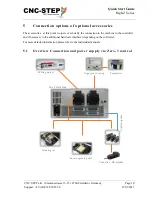
However, the milling motor can be turned on/off via the relay socket 1 (Rel.1) Zero-3 control via 
software or program. 

-


  Make sure that the control is turned off. 

-


  Connect the power cord to the socket 1 (Rel.1) Zero-3 controller. 

Of course, milling motors by other manufacturers can be connected in this way.  

You should also read the notes from page 6 for max. current consumption. 


5 .3


Nog a  s pra y  co olin g  w it h  sol e noi d  va lve  

Art. 350100  Noga spray cooling - without solenoid valve for manual operation 

Art. 350110  Noga spray cooling - automatic control via solenoid valve 

Art. 310250  Vacuum pump / compressor -0.7 bar / 2.5-3.0 bar 

 
The Noga spray cooling requires an air pressure of min. 2.5 bar. from a compressor. This should be 
designed for continuous operation. For this application we have a small, handy pump in the 
program (see above).  

Via solenoid valve, the air supply from the compressor can be automated by software or program. 
This is recommended by us. This has the advantage that lubrication is only done when it is 
necessary. 

-


Make sure that the control is turned off. 

-


Connect the power adapter to the socket 2 (Rel.2) Zero-3 controller. 

Summary of Contents for High-Z S-720 T

Page 1: ...Status 30 05 2017 Quick Start Guide High Z Series https www cnc step de en...

Page 2: ...rt 49 0 2831 91021 50 27 09 2013 High Z Series Short Description This Quick Start Guide will help you with the initial start up of the machine It also includes optional accessory that is connected dir...

Page 3: ...ling with solenoid valve 11 5 4 Inverter and HF spindles 12 5 5 Granitograv and laser engraving unit 12 6 SOFTWARE INSTALLATION 13 6 1 KinetiC NC 13 6 1 1 CncPod 13 6 1 2 Connecting Hardware 14 6 2 Wi...

Page 4: ...Quick Start Guide High Z Series CNC STEP e K Siemensstrasse 13 15 47608 Geldern Germany Page 4 Support 49 0 2831 91021 50 27 09 2013 7 CUSTOMER SERVICE 24...

Page 5: ...Y Motor connection cable Y axis D Sub 9pol Z Motor connection cable Z axis D Sub 9pol ST Control line ST Lug Ground Connection The miniXLR jack provides the option of connecting extensions without ad...

Page 6: ...roller 2 1 Front side 7 8 1 2 3 4 5 6 9 Front side Overview 1 Connector D Sub 9pol for motor X1 2 Connector D Sub 9pol for motor X2 3 Connector D Sub 9pol for motor Y 4 Connector D Sub 9pol for motor...

Page 7: ...voltage switchable via relay 1 6 Socket 2 115 240V depending on input voltage switched via relay 2 7 Ground High Z series 03 2015 Note on the sockets 1 2 The two sockets are with two relays switchable...

Page 8: ...rt 49 0 2831 91021 50 27 09 2013 3 Connecting the machine to the Zero 3 control Make sure that the control is turned off Connect all 5 cables with the Zero 3 controller Make sure that you back up all...

Page 9: ...er step motor can be operated as the fourth axis In addition to this port a 12 24V supply for an oscillation motor and the connection for a further reference switch are supplied Make sure that the con...

Page 10: ...his point we just cover briefly the connection to the machine to the controller and if necessary to the additional hardware interface depending on the software For more detailed information please ref...

Page 11: ...ocket 1 Rel 1 Zero 3 control via software or program Make sure that the control is turned off Connect the power cord to the socket 1 Rel 1 Zero 3 controller Of course milling motors by other manufactu...

Page 12: ...u back up all connections with the knurled screws from loosening Observe the notes from page 6 for max Power consumption Caution Inverter and HF spindles that have higher performance can also be used...

Page 13: ...machine type Please select one from the list Everything else is well explained in the two manuals and in the online help including instruction videos These can be found in the software KinetiC NC unde...

Page 14: ...onnector is only required with the corresponding accessories and is then also connected to the Zero 3 controller The CncPod is connected to the PC via a network cable If the simultaneous use of the In...

Page 15: ...tions and prices provide the right solution for beginners and model makers as well as semi professional use or for demanding industrial plants Here is an overview of all WinPCNC versions Zero 3 contro...

Page 16: ...ng the computer to the Zero 3 control The connection of the computer to the Zero 3 controller depends on the software and the associated additional hardware see page 12 Make sure that the control is t...

Page 17: ...on the software version on the LPT USB or serial interface In WinPCNC USB installation and configuration is complete In this version WinPCNC determines the interface automatically With other versions...

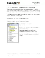
Page 18: ...ces on expansion cards interface cards it may be that this is a multifunction adapter or similar in the Device Manager Select the interface to which you have connected to the machine Go to the propert...

Page 19: ...hich interface you have connected to the control If the PC has no COM port it is possible to work with a USB Serial converter This adapter then emulates a COM interface see below COM4 Art 400305 Digit...

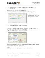
Page 20: ...entered For professional the correct COM port yellow must be selected 6 2 7 Entry LPT2 port only Economy If you need more inputs and outputs for machine extensions you can use the second LPT port This...

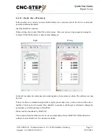
Page 21: ...using the example USB The hardware is detected and displayed Right Wrong In the left example the communication is taking place the machine is online The software can now be used If there is still no...

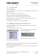
Page 22: ...are you will get the necessary instructions and the license code from us For preconfigured computers of course this has already happened 6 3 2 Milling program generation with KinetiC NC After completi...

Page 23: ...inPCNC DIN ISO The program now needs the WinPCNC path This is normally found automatically and only needs to be confirmed Confirm once the WinPCNC exe and then the WinPCNC For further information plea...

Page 24: ...NC STEP e K Siemensstra e 13 15 D 47608 Geldern Phone 49 0 2831 91021 50 Mo Fr 07 00 am 3 00 pm Mobile 49 0 2831 91021 20 Only in urgent cases Mo Thu 3 30 pm 6 00 pm Fax 49 0 2831 91021 99 E Mail supp...

Reviews: