Operating instructions
T-Rex N-Serie (Stepper)
CNC-STEP GmbH & Co. KG ▪ Siemensstrasse 13-15 ▪ 47608 Geldern ▪ Germany
Page 39
Support: +49 (0)2831/91021-50
07.03.2022
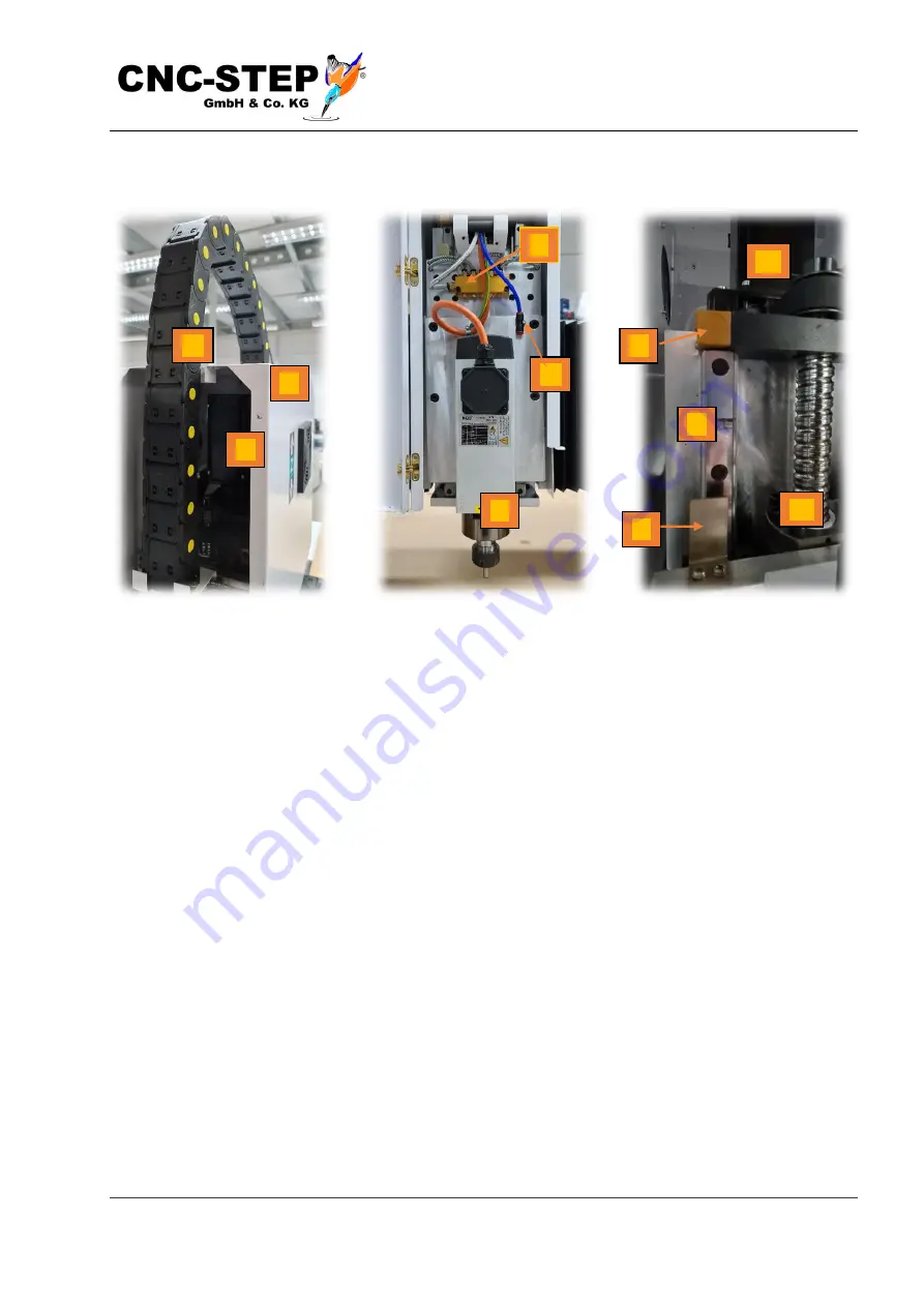
Fig.8: Z-axis
Fig.8.1: Z-axis
Fig.8.2: Z-axis
4 . 3 . 3
Z -axis
1. Z-axis
7. Homing switch, inductive
2. Protective Cover
8. Activator Homing switch
3. Cable Chain
9. Linear guide
4. Distributor central lubrication
10. Ball screw
5. Air connection for optional accessories
11. Stepper motor with timing belt
6. HF Spindle
The two profile rail guides (Fig. 8.2 / 7) guide the Z-axis. With help of the Ballscrew (Fig. 8.2 / 8),
the Z-axis is moved up and down on the profile rails. The transfer from the stepper motor to the
ball screw is carried out via a timing belt with a ratio of 1:1.
10
6
7
4
1
8
3
9
11
2
5


