background image

14

pasted on the auxiliary operating platform, the size of the material should within the scope of 90X90mm.

Meanwhile, the initial point of this file is on the top left corner.

The application of engraving machine is easy, which can be summarized as: clamping materials,

tool setting, and engraving. However, just as operating the computer, some people use computer just

for entertainment, so it lacks of required skills; some people make design for creation, so they make

great efforts for it. Therefore, the same computer may play different roles for people with different

requirements. It is the same for the engraving machine, because it is only a tool, and if you want it to

play a more important role and engrave better objects, you must have the ability to "send command" to

it. The command that can be executed by the engraving machine is called "processing code", and in

order to produce these "processing codes", you have to learn some software.

------------------------------------------------------------------------------------------------------------------------------------------------

Application of tool setting gauge

Tool setting gauge is an auxiliary tool for Z axis when it is setting the tool, and this function is only

restricted for the use of R2.63 version in Mach3. However, tests have not been conducted for other

versions, so support is not provided.

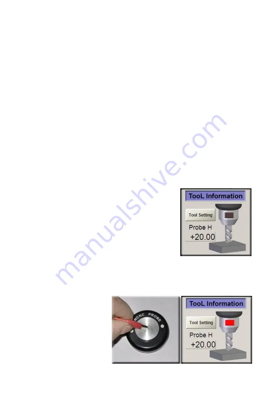
Attention: before using the tool setting gauge, you must first

measure its accurate thickness through vernier caliper, because this

value will directly influence the accuracy of tool setting; as it is

shown in the picture, input the value of the thickness to the character

box of "PROBE-H" (such as inputting 20), and then you must press

the "Enter" key to save this value.

Important: every time before applying the tool setting gauge, you

should first touch the surface of the tool setting gauge through the clamp on the red cable, to check

whether the indicator light on the tool setting interface is turned to red or not. If it is turned to red, it

means that this function can be used normally. If not, you should check whether the cable of the tool

setting gauge is connected well, or

whether

you

forgot to

make

the

setting but you have reinstalled this

software.

Summary of Contents for 3020Z-DQ

Page 1: ...0 Three axis CNC engraving machine USER GUIDE FOR 3020Z DQ 3040Z DQ Web site www lybga cn official agency www usbearth cn ...

Page 2: ... machine in good operating state and also lengthen its service life This engraving machine is a mechatronics processing tool so operators should grasp relative professional knowledge to be proficient in using this machine This manual only provides instructions to the application environment and operation requirements of this machine while not involving other professional knowledge that relate to c...

Page 3: ...oftware Control software Mach3 is recommended EMC2 and Kcam4 can also be applied and consult software providers for detailed information Design software ARTCAM PowerMill and TYPE are commonly used but there are also many kinds of other professional software Important statement we only sell engraving machine but not including computer and relative software The software mentioned in this manual is o...

Page 4: ... machine 5 Mach3 Software settings Trial run and manual control test for the machine Definition of triaxial coordinate To use your engraving machine 10 Primary engraving practice Install auxiliary operating platform for your engraving machine Secondary engraving practice Application of tool setting gauge Control the spindle motor through software Notice for machine maintenance and repair 3 ...

Page 5: ...4 To know your engraving machine Composition name of the machine Sketch map of installation and wiring ...

Page 6: ...instructions about installation in the Mach3 software manual before installing the software Attention do not open it after installing the software Y ou must first reboot the computer immediately and then open the software for settings After restart the computer The two files are copied to the installation directory and replace the original file software parameters settings Please refer to the foll...

Page 7: ...6 ...

Page 8: ...7 ...

Page 9: ...feel that under the condition without electricity they may be easily turned by hand Then plug in the electricity supply and turn on the POWER switch three step motors will be self locked at this time Turn the hand wheel by hand again you may fell that it is Slightly tight than the moment without electricity This states that the machine can be controlled now and you can send out an order to control...

Page 10: ...e operate or not If it is abnormal please contact with your dealer to deal with it Definition of triaxial coordinate The following is the reference drawing of the triaxial coordinate definition provided by us During the process of trial run if we found the running direction of the axis is incorrect we can change the Dir LowActive in the Motor Outputs of MACH3 to adjust it This coordinate definitio...

Page 11: ...ng of graphic pictures and texts Let s do the primary engraving practice by taking the right picture as an example This is a simple graphic engraving of pictures and texts and it is also the main purpose of engraving machine Step one Clamp materials According to the picture below fix the materials prepared for engraving on the operating platform of engraving machine Step two Tool setting Tool sett...

Page 12: ...ach3 software Now we will do the first engraving practice with this file Step four Begin to engrave Click Zero X Zero Y Zero Z respectively to reset the coordinate of X Y Z axial important Turn on the POWER switch on the electrical cabinet and then turn on the SPINDLE switch now the spindle motor may begin to move slowly Pay attention that when the principal axis moves clockwise it is correct if n...

Page 13: ...operating platform Why it is necessary to install an auxiliary operating platform In order to not damage the original operating platform when doing cutting operation We usually cut some boards with the engraving machine but if without the auxiliary operating platform it may cut the operating platform in the process of cutting the board thus permanently damaging the operating platform Therefore we ...

Page 14: ...hesive tape on the back of the double color plate Paste it on the milled plane of the auxiliary operating platform and press it to make it stickfast Tool setting Begin to engrave Get engraved works Display the finished products There is a file in the tool path for machine test of the random CD with the file name of shuangseban nc The area of this engraving file is about 75 85mm Because the double ...

Page 15: ...ware Application of tool setting gauge Tool setting gauge is an auxiliary tool for Z axis when it is setting the tool and this function is only restricted for the use of R2 63 version in Mach3 However tests have not been conducted for other versions so support is not provided Attention before using the tool setting gauge you must first measure its accurate thickness through vernier caliper because...

Page 16: ...Z axis may slowly decline When the tool tip touches the surface of the tool setting gauge it may immediately stop and then automatically return upward 5mm Take away the tool setting gauge and then the tool setting is completed Attention that the coordinate data on the Z axis should not be zero at this time Control the spindle motor through software This machine supports MACH3 software to control t...

Page 17: ...high speed Dragging the green bar upward and downward through the mouse can change the rotational speed of the principal axis Then click the Spindle CW F5 button the principal axis may stop You may also add the M03 and M05 code in the program to make the principal axis start automatically at the time of engraving and also make it stop automatically after finishing engraving You can refer to the SP...

Page 18: ...sure that each line in the drag chain is loose At the time of engraving these cable lines need to do flexure operations repeatedly so if the line is tight it may easily lead to the broken of internal copper wire thus causing poor contact In this way it may further let the electric motor out of control Check all the screws every month and tight the screws in time if they are loose The spindle motor...

Reviews: