Model SH-2012AH-QG
Cutting Machine
(
C002
)
33
8.3. Arrangement and Layout of Pattern Element
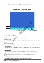
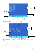
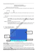
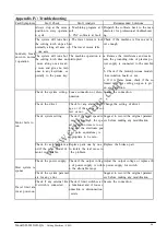
After pattern element is selected as per the above-mentioned procedure, the system will prompt at the upper
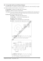
right corner to input parameters for the pattern, as show in Fig. 8.2
【
F1
】
Workpiece:
To machine into workpiece that is solid internally.
【
F2
】
Hole:
To machine into hole that is solid externally.
【
F3
】
Rotate:
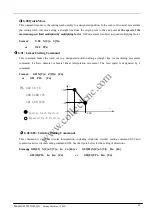
The system will prompt to input rotation angle and press [ENTER] or [F6] to acknowledge. The
pattern rotated such an angle will appear. Counterclockwise direction is taken as positive angle.
【
F4
】
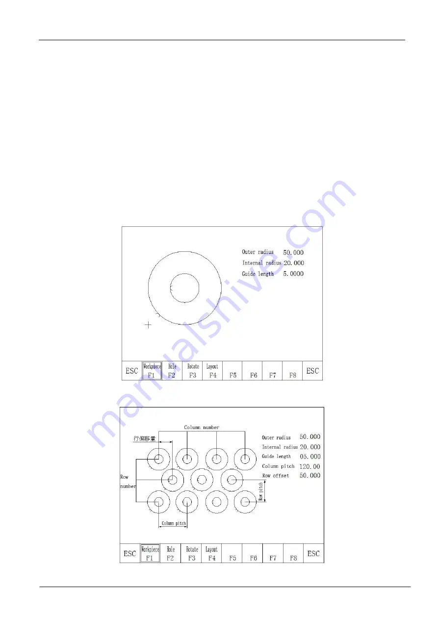
Layout:
The system will prompt user to provide:
Row number
----Row number of machined parts array
Column number
----Column number of machined parts array
Row pitch
----Distance between rows.
Column pitch
----Horizontal distance between machined parts
Row offset
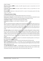
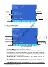
----The deviation of raw misplacement, as shown in Fig. 8.3.
Fig. 8.2 Pattern setting menu
Fig. 8.3 Schematic diagram of part layout
www.collectcnc.com


