Model SH-2012AH-QG
Cutting Machine
(
C002
)
49
Appendix V: Wiring Instructions for Extended External Manual Control Box
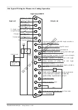
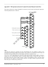
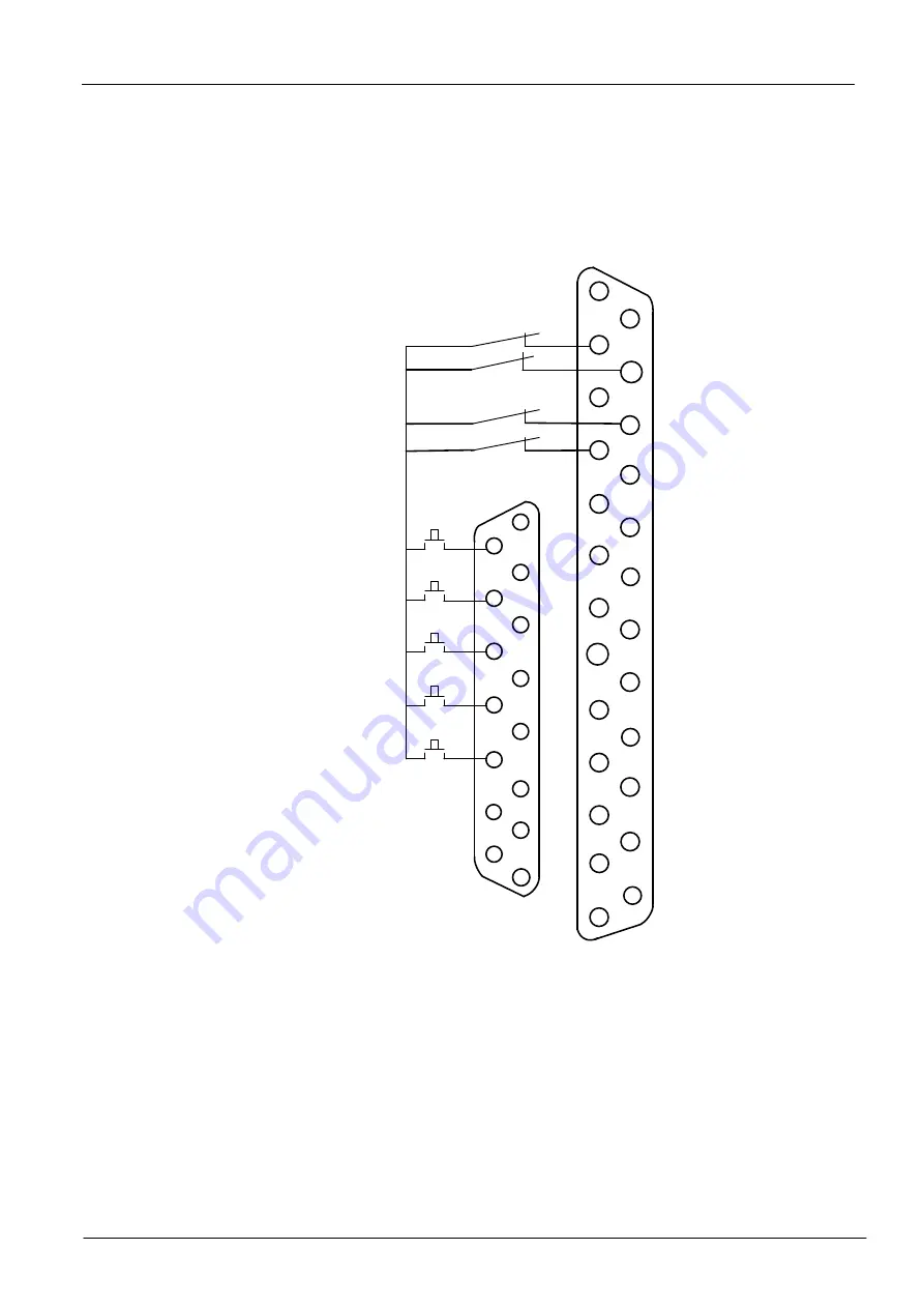
The system is allowed to connect a handheld (or wireless) external control box through 8 input ports.
The wiring instructions are as follows:
1
9
2
3
4
5
6
7
8
1
2
3
4
5
6
7
8
9
Input/output
(DB25)
XS12
XS8
Start key
Pause key
Emergency stop key
Backspace key
X-axis positive movement
X-axis reverse movement
Y-axis positive movement
Y-axis reverse movement
Piercing key
Com/man. ctrl.(DB15)
10
11
12
13
14
15
10
11
12
13
14
15
16
17
18
19
20
21
22
23
24
22
Notes:
1.The start key, pause key, emergency stop key and backspace key are required to connect to the
input/output port through normally-closed contacts. These four keys are enabled at system booting and
not affected by the possibility if the external manual control box is enabled or not.
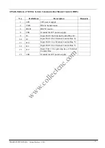
2. X+, X-, Y+ and Y- piercing keys are connected to the system auxiliary connector (DB15), which are
required all to use normally-closed contact or normally-opened contact. It means the logic of the 5
ports must be the same, all NO contact or all NC contact. The availability of these 5 external control
keys depends on the option of external manual control box for height controller in parameter setting.
When the option is enabled, they will function.
www.collectcnc.com

