background image


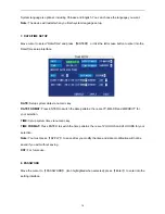
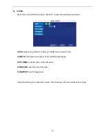
CHANNEL: 

ON: Means the channel is enabled for recording. 

QUALITY: 

There are three options: HIGHEST, HIGH and NORMAL, corresponding to HIGHEST, HIGH 

and NORMAL data stream standards. 

AUDIO: 

ON: Means audio recording for all channels is enabled, OFF: Means audio recording is disabled. 

REC.MODE: 

POWER UP: Means the device will start recording when it starts up. 

TIME: Recording as scheduled; you can tailor the setup schedule as follows. 


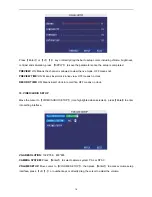
CHANNEL: 

You can select all channels or just one channel

Blue means selected


DAILY: 

There are three modes: ALARM, NORMAL and NO REC. If you select one mode, the whole day 

will be recorded in that mode. You can cancel recordings by pressing the 

Enter

 button; grounding 

means do not recording. Different colors mean different record modes: Red means alarm record, Green 

means normal record and Blue means no record

RECORD SIZE: 

There are 15min, 30min, 45min, 60min options; to record using the mode selected. 

Scroll to 

APPLY 

and press

 ENTER t

o save the new settings.   


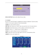
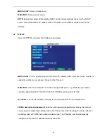
4. HDD (Hard Disk Drive) MANAGEMENT. 

Move the cursor to 

HDD

】(

Icon highlighted when selected

, press

Enter

to enter into the setting 

interface, and you can use direction keys or cursor to change the options. 


12 

Summary of Contents for 8 Channel H.264

Page 1: ......

Page 2: ...RECORD MODE 11 HDD MANAGEMENT 12 BASIC SETUP 13 SYSTEM LANGUAGE SETUP 13 DATE TIME SETUP 14 PASSWORD 14 DISPLAY SETUP 15 VIDEO AUDIO SETUP 16 ADVANCED SETUP 17 ALARM SETUP 17 SYSTEM INFO 18 MOTION DET...

Page 3: ...lucent GUI notes for selected menu items Optimized eight channel simultaneous playback Double level user management Supports live view parameter setting and copy playback video via network 1 2 1 PARAM...

Page 4: ...ADPCM Video code rate CIF 384 768 Kbps optional HD1 512 1024Kbps optional D1 512 1024Kbps optional Audio codec rate 32KB s Picture Processing and Storage Data storage SATA HDD storage optional Alarm A...

Page 5: ...VR and to prolong the life of the device please pay attention on following 1 When installing device please comply all the electric product safety criteria 2 Power and ground Do not touch the power soc...

Page 6: ...return to normal speed REV Reverse the video while playback press REW to switch press PLAY to return to normal speed POWER ON Reset the DVR to Power on and Power off mode Standby and Start Up LOGIN LO...

Page 7: ...window 2 The control shown when clicking the left button for volume adjustment and color adjustment is as follow a There is a box to show the volume on the volume adjustment interface Move the mouse...

Page 8: ...played at the same time 2 In the Motion Detection setting interface you can use the left button to drag the frame to set the motion detection area 2 1 3 MENU TREE You can control all the functionality...

Page 9: ...ng The steps to do this are Main Menu HDD Management Format After formatting the system will restart 2 SYSTEM LOGIN You can login from the USER LOGIN window as follows Input the device ID and user pas...

Page 10: ...Menu option 1 RECORD SEARCH Move the cursor to RECORD SEARCH Icon highlighted when selected press Enter t o enter into the setting interface There are three methods of searching records Method 1 Playb...

Page 11: ...options Press Enter and the content will be displayed in a list Instruction 1 FILE LIST CH the corresponding channel the recorded file belongs too SIZE is the displaying size of this file Unit MB TYP...

Page 12: ...disappear which means the selection has been cancelled You can start to export the selected recording files by pressing BACKUP as follows Instruction 1 When the available space on the backup device is...

Page 13: ...s selected DAILY There are three modes ALARM NORMAL and NO REC If you select one mode the whole day will be recorded in that mode You can cancel recordings by pressing the Enter button grounding means...

Page 14: ...han 500MB the system will stop recording and a prompt will display in live view please shutdown and replace HDD FORMAT Move cursor to select device and press APPLY to start formatting 5 BASIC SETUP Mo...

Page 15: ...ia numeric key DATE FORMAT Press ENTER to switch the date patterns there are YY MM DD and MM DD YY for your selection TIME Setup system time via numeric key TIME FORMAT Press ENTER to switch the time...

Page 16: ...Press number key to setup NETWORK PW CLEAN Select and apply will initialize the IE browser password 9 DISPLAY SETUP Move the cursor to BASIC SETUP Icon highlighted when selected press Enter to enter...

Page 17: ...live view OFF means no clock RECORD TIME ON Means insert clock in record file OFF means no clock 10 VIDEO AUDIO SETUP Move the cursor to VIDEO AUDIO SETUP Icon highlighted when selected press Enter t...

Page 18: ...nitoring System maintenance PTZ and Network settings 12 ALARM SETUP Move the cursor to ALARM SETUP Icon highlighted when selected press Enter to access the settings interface I O CHANNEL Each channel...

Page 19: ...larm Output Buzzer and Post REC Output When an alarm is triggered the alarm output time will be 0 second 10 seconds 20 seconds 40 seconds and 60 seconds BUZZER Buzzer calling time setup when alarm is...

Page 20: ...onding setting and press Enter to enter the regional setting interface red area mean motion detection is activated in that area transparent block means motion detection is not activated in that area P...

Page 21: ...ning red means this is selected press Enter to enter into system maintain setup interface AUTO RESET When this is on you can setup the time for device to restart SYSTEM UPDATE Copy the update file to...

Page 22: ...TZ connected PROTOCOL Select the protocol for the PTZ there are two protocols to select The default is Pelco D BAUD RATE Select the baud rate for your PTZ the options are 1200 2400 4800 and 9600 DATA...

Page 23: ...cess the interface as below MEDIA PORT Transfers video data between the client and device WEB PORT Setup the port for Internet Explorer to connect to via HTTP IP ADDRESS Setup the IP address and press...

Page 24: ...nother server please change to other free port WEB PORT HTTP Port Default 80 If admin change WEB port to e g 8088 the port number should be added behind IP http 192 168 15 145 8088 should input into I...

Page 25: ...OFF If there is a DDNS service setup to ON SERVICE Three services to select 3322 DynDNS Perfecteyes HOST NAME Input the name of the host server USERNAME Input the name of the user PASSWORD Input the p...

Page 26: ...SER LOGIN Input the local IP Address of the DVR in the Address box of the IE browser e g http 192 168 0 102 if the web port number is set as 80 then no extra information is necessary If the port numbe...

Page 27: ...ssword to use are the same as the ones used to login to the DVR PASSWORD Administrator has all authorities operator has limited authorities they can only watch playback Please change the unit No and d...

Page 28: ...VR Quick start to record video on all channels The left upper corner of each channel has the normal recording video symbol R click the icon to switch between single screen quad nine 16 and split Volum...

Page 29: ...ht mouse button in the live view screen click open all windows or close all windows to quickly open close all windows 3 3 2 REPLAY Click REPLAY to enter into the playback interface Click right in the...

Page 30: ...29...

Page 31: ...th of May Select the channel and type at the bottom of the calendar Click SEARCH and the result will display as follows Double click one of the listed recorded videos to playback The file icon will ch...

Page 32: ...e conversion progress bar shown below will show the progress of conversion 3 3 3 SETUP Click to enter into the setup interface this interface includes Record Alarm PTZ Network Setting and System infor...

Page 33: ...3 3 3 2 ALARM SETTING Click ALARM to enter into the setup interface you can check and change the parameter settings in the same way as using the User Interface of the DVR 32...

Page 34: ...n check and change the parameter settings in the same way as using the User Interface of the DVR 3 3 3 4 NETWORK Click to access the setup interface you can check and change the parameter settings in...

Page 35: ...to allocate for traffic over the Internet This bandwidth does not include audio FILE SAVE PATH The save path of captured picture and recording video IE login password and DST settings which can be se...

Page 36: ...move the cursor to setup and control PTZ OK Confirm operation in the PTZ control panel under live view 2 Control button MUNE EXIT Enter into main menu under live view or exit sub menu REC Recording A...

Page 37: ...Video input For connecting analog video signal input BNC 4 Audio Input For connecting audio signal Alarm Input I O alarm input 4 for 4CH DVR and 8 for 8CH DVR Alarm Output I O output for alarm RS485 R...

Page 38: ...3 SYSTEM NETWORK DIAGRAM The example below shows an 8 Channel System but the connections for a 4 Channel System work in the same way 37...

Page 39: ...can damage it permanently Please install the HDD using the following steps 1 Open the cover of the DVR and then you will see one HDD plate as follow 2 Connect HDD line as follow 3 Affix HDD on HDD pla...

Page 40: ...upply is not enough The front end video signal instability High temperature too much dust or a bad DVR operating environment The main board is not connected with other boards correctly The hardware of...

Page 41: ...with real time images such as bad image color or serious brightness distortion Answer If PAL and NTSC is not correctly selected on the BNC output the images will be in black and white DVR is not compa...

Page 42: ...n If you want to stop recording please make sure the system is not set to record at the current time 11 Question Motion detection is not working Answer The setting of motion detection area is not corr...

Page 43: ...ally install ActiveX control again Please install DX8 1 and upgrade your video card driver 15 Question There is no picture or picture is not clear when you preview the recording or playback the record...

Page 44: ...rom misuse or neglect A unit that has been modified or incorporated into other products or is used for institutional or other commercial purposes Loss of customer s software firmware information or me...

Reviews: