background image


TECHNICAL SPECIFICATION 

TITLE:


IEC INSTALLATION INSTRUCTION 
MANUAL FOR THE CRYSTALLINE 
SOLAR PHOTOVOLTAIC MODULE


SPEC. NO.: 

CNPV-PS-M-S0010-IEC 

REVISION: J 

EFFECTIVE DATE: 

July 2012 

AUTHOR(S):

  Bypina Veerraju Chaudary, Yang Xiaowu 

Page 3 of 15


CNPV Dongying Solar Power Company Limited,  

Shengli Industry Park, Dongying City, Shandong Province 257000, PRC 

http//www.cnpv-power.com    E-mail: 

marketing@cnpv-power.com

  Tel: +86-546-7795555, Fax: +86-546-7795777 


8. MOUNTING AND NOTES 

 
Systems should be installed by qualified personnel only. It involves electricity, and can be dangerous if the personnel 
are not familiar with the appropriate safety procedures. 

 
The Module frame is made of anodized aluminum, and therefore corrosion can occur if the Module is subject to a 
salt water environment with contact to a rack of another type of metal (Electrolysis Corrosion). If required, PVC or 
stainless steel washers can be placed between the SPV Module frame and support structure to prevent this type of 
corrosion. Module support structures that are to be used to support SPV Modules at correct tilt angles should be wind 
and snow load rated for use by the appropriate local and civil codes prior to installation. 

 
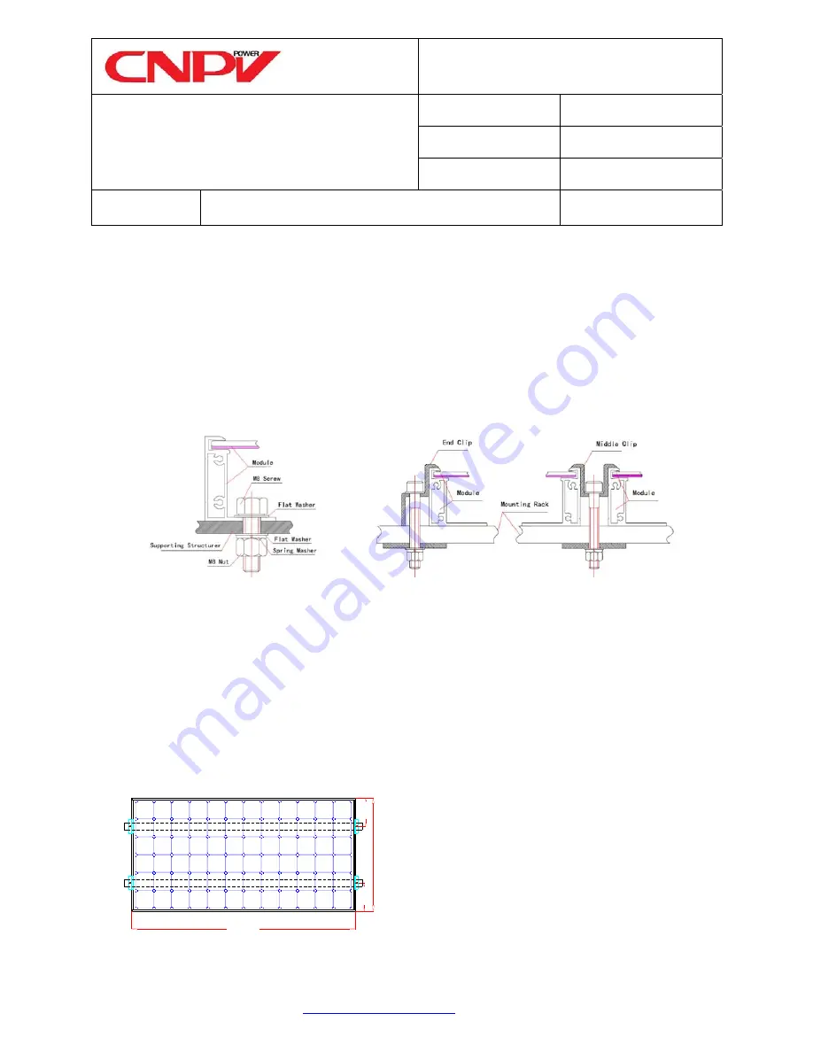
CNPV SPV Modules can be mounted as following method: 


Figure 2 Mounting Method a and b 

 
a)


Using corrosion-proof screws (M8) on the existing installing holes (see drawing 1, 3, 5 & 7) in the Module 
frame. The frame of each Module has 4 or 8 mounting holes (12mm×9mm) used to secure the Modules to 
supporting structure. The Module frame must be attached to a supporting rack using M8 stainless steel hardware 
together with spring washers and flat washers in four places symmetrical on the SPV Module. See method a of 
figure 2. The applied torque is about 8 Newton-meters. 

b)


 Using suitable Module clamps on the Module frame, see method b of figure 2. The module frame must be 
attached to supporting rack using M8 stainless steel hardware together with corrosion-proof clips in four places 
on the SPV module. See drawing 10, 12, 14 & 16, 

with clamping clip, 

for positioning of clamping clips. The 

applied torque is about 8 Newton-meters. See figure 3 if clamping mounting is on short frames of the module. 


W

idth

1/

4W

1/4

W

Length


c)


Insertion System 

Method a: Using corrosion-proof 

screws on existing Installation 

Method b. Using suitable module 
clamps on the module frame 

Using Short sides for module clamping. W 
means module width, and 1/4W means 
permissible clamping range.  
 

Figure 3. Mounting on short frames. 

Summary of Contents for CNPV-PS-M-S0010-IEC

Page 1: ...IEC INSTALLATION INSTRUCTION AND MAINTENANCE MANUAL FOR CRYSTALLINE SOLAR PV MODULE...

Page 2: ...a range of sizes designed to meet the requirements of the most demanding energy and power users worldwide 2 POWER MODULE CNPV Solar Photovoltaic Modules consist of a series of electrically interconne...

Page 3: ...ltaic Modules especially during the winter months when the arc of the sun is lowest over the horizon Shading causes loss of output even though the factory fitted bypass diodes of the SPV Module will m...

Page 4: ...ropriate local and civil codes prior to installation CNPV SPV Modules can be mounted as following method Figure 2 Mounting Method a and b a Using corrosion proof screws M8 on the existing installing h...

Page 5: ...surface of the building wall or roof Clearance between the Module frames and surface of the wall or roof is required to prevent wiring damage and to allow air to circulate behind the Module The recom...

Page 6: ...ould have access to these Modules To reduce the risk of electrical shock or burns modules maybe covered with an opaque material during installation to avoid electrical shocks or burns Do not touch liv...

Page 7: ...e considered to meet the requirements for Safety class II 14 MAINTENANCE Under most weather conditions normal rainfall is sufficient to keep the SPV Module glass surface clean If dirt build up becomes...

Page 8: ...35 15 160 34 5 4 65 43 0 5 15 IEC61215 IEC61730 1000VDC 10 17 2 CNPV 165M 165 35 2 4 70 43 4 5 20 17 2 CNPV 170M 170 35 8 4 75 43 8 5 25 17 2 CNPV 175M 175 36 6 4 80 44 2 5 30 17 2 CNPV 180M 180 37 2...

Page 9: ...4 225 27 8 8 10 33 8 8 60 23 3 CNPV 230M 54 230 28 0 8 20 33 9 8 70 23 3 CNPV 235M 54 235 28 3 8 30 34 0 8 80 23 3 CNPV 240M 54 240 28 7 8 35 34 1 8 85 23 3 60pcs 156 156mm SPV Module Mono Crystalline...

Page 10: ...10 33 8 8 60 23 3 CNPV 230MB 54 230 28 0 8 20 33 9 8 70 23 3 CNPV 235MB 54 235 28 3 8 30 34 0 8 80 23 3 CNPV 240MB 54 240 28 7 8 35 34 1 8 85 23 3 60pcs 156 156mm SPV Module Black Mono Crystalline Si...

Page 11: ...4 1 8 50 23 3 CNPV 230P 54 230 28 4 8 10 34 3 8 55 23 3 CNPV 235P 54 235 28 6 8 20 34 5 8 65 23 3 60pcs 156 156mm SPV Module Poly Crystalline Silicon CNPV 210P 1650 992 35 20 210 29 2 7 20 36 4 7 80 2...

Page 12: ...CNPV 230PB 54 230 28 4 8 10 34 3 8 55 23 3 CNPV 235PB 54 235 28 6 8 20 34 5 8 65 23 3 60pcs 156 156mm SPV Module Black Poly Crystalline Silicon CNPV 210PB 1650 992 35 20 210 29 2 7 20 36 4 7 80 20 21...

Page 13: ...86 546 7795555 Fax 86 546 7795777 4 9 12 INSTALLING HOLE 1581 2 948 7 5 4 4 12 DRAIN HOLE 2 4 GROUNDING HOLE GROUNDING MARKING 809 2 4 4 6 DRAIN HOLE 4 4 4 DRAIN HOLE 316 5 316 5 Section A A magnified...

Page 14: ...CE 1202 4 12 DRAIN HOLE 8 9 12 INSTALLING HOLE 2 4 GROUNDING HOLE 992 2 702 For normal installation 1200 Typical GROUNDING MARKING 942 4 4 5 4 DRAIN HOLE 140 140 1482 2 390 390 For High wind and snow...

Page 15: ...l 86 546 7795555 Fax 86 546 7795777 1 9 35 35 1 8 1 5 990 4 12 DRAIN HOLE 8 9 12 INSTALLING HOLE 2 4 GROUNDING HOLE 992 2 Section A A magnified 941 4 4 5 4 DRAIN HOLE 330 330 1200 Typical 1650 2 11 GR...

Page 16: ...86 546 7795555 Fax 86 546 7795777 1965 2 1177 941 4 R2 25 4 DRAIN HOLE 2 4 GROUNDING HOLES 4 9 12 INSTALLING HOLE GROUNDING MARKING 4 R6 DRAIN HOLE Section A A magnified 11 394 394 35 40 2 0 992 2 120...

Reviews: