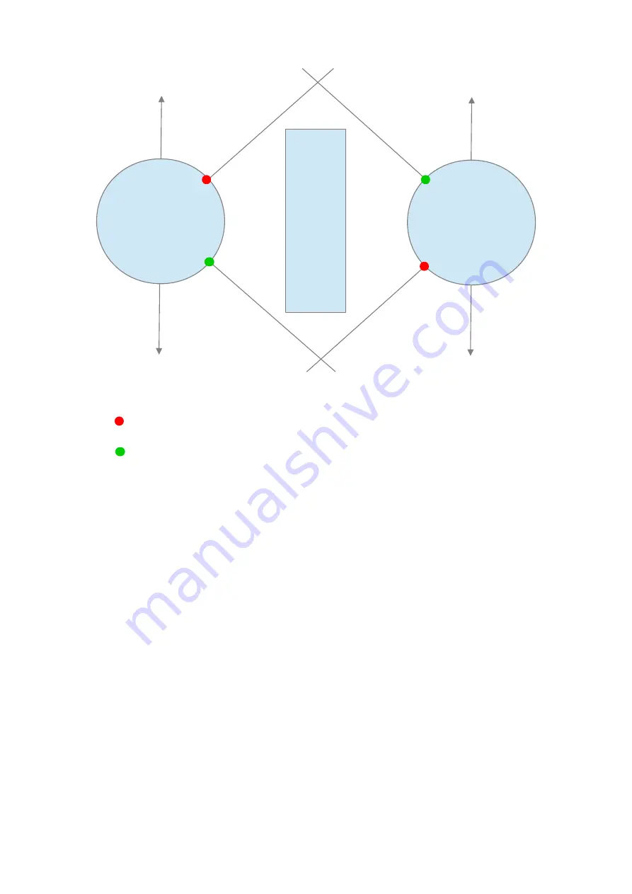
azimuth low limit
azimuth high limit
In this case both antennas are installed facing the FWD. In some cases one of the antennas is
installed facing the AFT. In this case adjust the angles following this consideration.
Just to give an example, in the previous schematic the values for Antenna A are around:
low limit : 30°
up limit : 150°
For Antenna B:
low limit : 210°
up limit : 330°
The values that you can insert are filtered by the logic and if you change something with a not
correct value the system will activate the flag “not valid” which can be found below the buttons
“New” and “Submit”. For example the azimuth limits are limited to 0° to 359° and the IP address
cannot go over 255.255.255.255. Inside the green circle you can find the Not Valid flag active and
the reason of the activation.
In this case a not valid IP address was been inserted (392.xxx.xxx.xxx).
ANTENNA A
ANTENNA B
MAST
FWD=0°
FWD=0°
BLIND
SECTOR
BLIND
SECTOR
AFT=180°
AFT=180°
Summary of Contents for Smart Antenna Selector
Page 1: ......


