background image

Sampling Data Logger User Manual


CO2Meter


PAGE 

7

of 

16


Quick


Start


Guide


Make


sure


you


read


through


these


instructions


thoroughly


before


using


your


meter.


This


guide


will


help


you


familiarize


with


your


meter


in


order


to


be


as


productive


as


you


need


to


be


in


the


least


amount


of


time


possible.


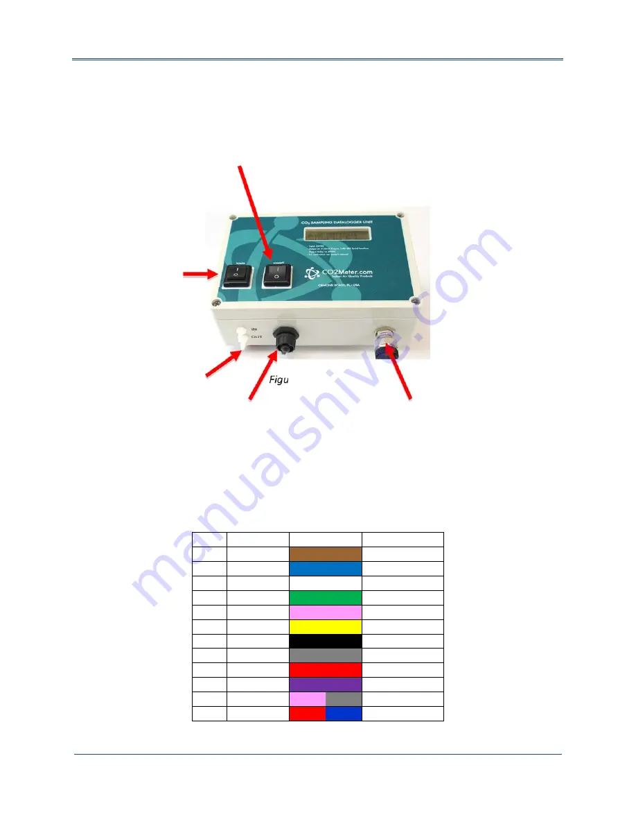
Figure3:


Components


Power


Source


These


meters


are


powered


by


connecting


to


a


suitable


24VDC


power


source.


This


is


very


convenient


for


permanent


installations.


Outputs


and


Cable


Legend


Pin


#


Wire


Color Color


Legend

Description


1


Brown


CO2


4

20mA

‐ 

2


Blue


N/O


Relay


3


White


CO2


4

20mA+


4


Green


RS

485


Ground

5


Pink


N/C


Relay


6


Yellow


COM


Relay


7


Black


Power


Ground


8


Grey


O2


4

20mA

‐ 

*


9


Red


Voltage


Input


10


Purple


O2


4

20mA

‐ 

*


11


Pink/Grey


RS

485


B


12


Red/Blue


RS

485


A


Table


1:


Cable


legend.


(*


O2


models


only)


Mini


USB


Port


Connect


to


PC


for


meter


configuration,


data


transfer,


and


USB


charging


M12


Connector


12

pin


RS

485


connection


for


24VDC


power


source


and


controller


interface


(for


PLC,


MODBUS,


etc.)

Power


Switch


Turns


the


unit


on/off


Barb


Fittings


Connect


to


sampling


system


for


closed


loop


sampling


Pump


Switch


Turns


pump


on/off

Summary of Contents for CM-0052

Page 1: ...Copyright 2016 CO2Meter Inc All Rights Reserved User Manual CO2 Sampling Data Logger NEMA4 Models CM 0052 CM 0152 CM 0154 CM 0132 CM 0153 CM 0155...

Page 2: ...8 POWERING THE UNIT 9 LCD DISPLAY IF APPLICABLE 9 USAGE PUMP ONLY 9 Closed Loop Operation 9 Open Loop with Environmental Exhaust 9 THEORY OF OPERATION 10 0 1 and 0 30 Units Only 10 CALIBRATION 11 0 1...

Page 3: ...ue opportunity to understand educate and provide product solutions that meet the customers needs while exceeding their expectations for reliability and service Our continued product innovation in comb...

Page 4: ...ns basic safety precautions should always be followed when using electrical appliances including the following 1 READ ALL INSTRUCTIONS BEFORE USING THIS METER 2 INSTALL GasLab SOFTWARE BEFORE CONNECTI...

Page 5: ...dity out Use anywhere humidity is very high 95 SKU CM 0103 GasLab Software IMPORTANT MAKE SURE TO INSTALL SOFTWARE BEFORE CONNECTING YOUR METER TO YOUR COMPUTER Minimum System Requirements To utilize...

Page 6: ...manual in PDF from this page Please read the GasLab s user manual carefully to become more familiar with how the software works so that you can get the maximum benefit from this useful tool Install t...

Page 7: ...uts and Cable Legend Pin Wire Color Color Legend Description 1 Brown CO2 4 20mA 2 Blue N O Relay 3 White CO2 4 20mA 4 Green RS 485 Ground 5 Pink N C Relay 6 Yellow COM Relay 7 Black Power Ground 8 Gre...

Page 8: ...uration These meters feature an internal memory capable storing data when not attached to a personal computer These units will allow you to simultaneously read and store CO2 concentration level data D...

Page 9: ...licable The Liquid Crystal Display LCD screen shows the following features CO2 in parts per million ppm for 1 and 5 models CO2 in percentage format for 30 65 100 Logging On Off Percentage of memory fr...

Page 10: ...hese units The primary contributor to sensor drift is the normal and unavoidable aging of the infrared light source within the sensor The ABC algorithm allows the CO2 sensor to dynamically shift its C...

Page 11: ...s follow a single point calibration routine that effectively shifts the zero point of the CO2 sensor Attach calibration gas to the unit and connect it to a personal computer Open the calibration scree...

Page 12: ...pm 5 Disconnect the calibration gas and wait 25 seconds The newly displayed data will now reflect the new sensor calibration If the sensor is still operating outside of its specified range repeat this...

Page 13: ...correct concentration level then close the window by clicking on the Save button NOTE DO NOT ADJUST THE SPAN VALUE Troubleshooting guide Symptom Issue Possible Cause Resolution Device Sensor is not re...

Page 14: ...C Minimum Voltage 18VDC Power Consumption 1Watt avg pump running Sensor Ratings Life Expectancy 15 years Maintenance Interval No maintenance required Warm up Time 1 min instant measurements Pump Chara...

Page 15: ...irs by you or by a third party No employee or reseller of CO2Meter com s products may alter this warranty verbally or in writing Liability All liabilities under this agreement shall be limited to the...

Page 16: ...ng Data Logger User Manual CO2Meter PAGE 16 of 16 Contact Us We are here to help For information or technical support please contact us support co2meter com 386 256 4910 Technical Support 386 872 7665...

Reviews: