O P E R A T I N G M A N U A L
8 0 0 . 7 4 9 . 2 7 6 1
w w w . c o a c h c o m m . c o m
7 0
Wireless Component Setup and Integration
The wireless portion of X-System is an add-on to the wired system. If the wired system is not set up properly or if there is a
problem with the dry pair or any aspect of the wired system, the wireless portion may not work correctly.
•
Walk Test the Radio Pack
— Walk testing is very important. If a user tests the units only standing right beside
the system unit, he may not discover potential frequency problems. Spread your Radio Packs out along the bench
area so they are not piled on top of one another. Walk test each unit from one end of the coach’s box to the other,
at a minimum. Effective system administrators walk the units on the entire grass surface. Listen carefully on both
the Control Unit and Radio Pack for “drop out.” Should you have an unacceptable amount of drop out or if the
signal sounds poor, you may wish to change antenna location. If a sub-system still does not function properly, set
it aside for work later. Remember not to turn off power to the unit, but turn off the TALK button for the unit.
»
If all wireless to wired (or wired to wireless) users sound too loud or too quiet to the other, use the Control
Unit’s Intercom Levels menu option to adjust the volume.
•
Turn Off the TALK Button On All Control Units and Radio Packs
— Now that setup of this particular wireless is
complete, turn off the TALK button on the Radio Pack. This will keep background noise to a minimum. Do NOT turn
off the power to the Radio Pack, only the TALK button. Repeat the above steps for all wireless units.
NOTE:
Also make sure that all talk lights on all wired BeltPacks are off during testing.
•
Re-Test All Units
— After you have completed the sub-system adjustments, you should go back and walk test
the units again. If you find that previously working units are now working incorrectly, you should re-evaluate the
changes made above.
If any unit is deemed not usable, turn off the power to that Radio Pack and store the Radio Pack away.
Understanding Link Quality
The Link Quality (LQ) is a numeric value that provides a real-time metric on the quality of communication between the radio
in the Radio Transceiver and the radio in the Radio Pack. The LQ serves as a diagnostic tool for proper system operation and
troubleshooting Radio Packs.
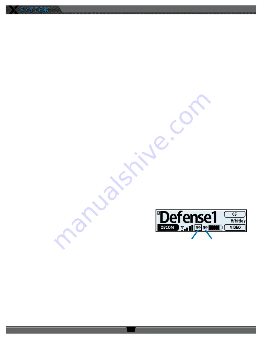
• With X-System, the receiving LQ signal is reported for both
the Radio Transceiver and Radio Pack. The Radio Pack’s on-
screen LQ indicator with the box around it is the Transceiver’s
LQ from the RP. If this LQ is lower than normal, then it is an
indication that you may have an issue related to interference,
the transceiver, or a cable connection. If only the RP’s LQ
is low, it could be an indication that you may have an issue
related to interference or the Radio Pack.
• What should the LQ value be during operation? — There is no
exact value that LQ will remain at during system operation.
Depending on what degree of outside interference or attenuation (blocking) is present, the LQ will fluctuate during
normal operation. Fluctuations in LQ can and will span a wide range of values. The lower the LQ, the poorer the
audio quality will be during operation. During start-up, within adequate range and no outside influences present,
the LQ should display “99” which is the highest LQ value a Radio Pack or Radio Transceiver can have.
• What if the LQ on a single Radio Pack is below “99” at start-up? — This depends on where the Radio Pack
is located at start-up, but if the other Radio Packs on the same Radio Transceiver are at “99” this is a good
indication that isolated radio issue exists within that Radio Pack. If the LQ value has dropped considerably lower or
if that unit is experiencing poor audio quality it may require service.
Link Quality
RP to RT
Link Quality
RT to RP
Figure 99: RP Primary Screen LQ Indicator


