12
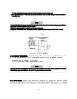
3-3. V-BELT DRIVE.
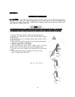
Motor speed is increased by V-belt drive to the male rotor's driving speed.
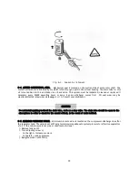
Fig 3-4. V-Belt drive
3-4. CAPACITY CONTROL.
All models provide capacity control, on-line/off-line control. Internal pressure is
vented to atmosphere at partially loaded or unload conditions whereby the motor idles for power saving
features.
3-5. LUBRICATION SYSTEM.
The lubrication system consists of oil cooler, oil separator, and controls the oil
temperature within an allowable limit. The oil circulates through the system by differential pressure.
3-6. AFTER COOLER / OIL COOLER.
The cooler assembly is consisting in heat exchanger, cooling fan, fan
motor and bracket.
After-cooler and oil-cooler are composed of corrugated fin and tube type with aluminum
material. Those fins remove the compression heat efficiently. Cooling fan exhausts the heat-exchanged air
through a ventilation duct to the outside of the enclosure.
3-7. OIL SEPARATOR
.
Spin-on type Oil separator is located at the air-end, which efficiently separates the oil
from discharged air.
3-8. OIL FILTER
.
Oil filter element is located at the air-end, which efficiently filtering foreign material from
circulating oil. The oil filter has from 5 to 10 micron paper cartridge, and it should be replaced every 1000 run
hours normally.
3-9. THERMOSTATIC VALVE.
This is the oil by-pass valve, Located in the oil cooler outlet pipe in order to
maintain adequate system temperature for efficient compression and protect to making water from compressed
air. The operating temperature is set 160
℉
.
3-10. MINIMUM PRESSURE VALVE.
Located in air-end discharge in order to maintain adequate system
pressure for efficient separation of oil, pressure setting is 57 psig. If less than 57 psig, adjust the screw to
maintain pressure on 57 psig or more.
3-11. AIR INTAKE FILTER.
The air intake filter is replaceable, dry-type filter with two-stage design. It consists
of an outside element of urethane and inside element of polyester.
3-12. INSTRUMENT PANEL.
Consists of start button, stop button, indicating lamps, synoptic display, control
panel and pressure gauge.
3-13 STARTER AND CONTROL BOX.
Consists of pre-wired direct starter for model CHSA-7.5M through
CHSA-30M and star-delta starter useable for model CHSA-30M optionally.
Summary of Contents for CHSA-10M
Page 31: ...27 AIR END NK40 ...
Page 33: ...29 AIR END NK60 ...
Page 34: ...30 Appendix B 1 PART LIST FOR MODEL CHSA 7 5M 1 2 ...
Page 35: ...31 1 PART LIST FOR MODEL CHSA 7 5M 2 2 ...
Page 36: ...32 2 PART LIST FOR MODEL CHSA 10M 1 2 ...
Page 37: ...33 2 PART LIST FOR MODEL CHSA 10M 2 2 3 PART LIST FOR MODEL CHSA 15M 1 2 ...
Page 38: ...34 3 PART LIST FOR MODEL CHSA 15M 2 2 ...
Page 39: ...35 4 PART LIST FOR MODEL CHSA 20M 1 2 ...
Page 40: ...36 ...
Page 41: ...37 4 PART LIST FOR MODEL CHSA 20M 2 2 ...
Page 42: ...38 C Wiring Diagram for Model CHSA 7 5 10 15 20M ...
Page 43: ...39 Appendix D 1 Outline Drawing for Model CHSA 7 5 10M ...


