16
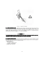
After securely tightening the plug at the oil filling port, run the unit to make sure there are no oil leaks.
⒢
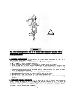
4-2-3 DRAINING CONDENSATION.
Moisture contained in intake air can be condensed into water during long
unloading time or when the unit is stopped, and this moisture is accumulates in the separator sump, Since the
water in a compressor system can cause deterioration of oil and internal rusting, do not neglect draining the
condensation at least on a daily basis. Draining should be performed before start-up since oil and condensation
have been sufficiently separated from each other. Open the drain valve at outlet of oil separator sump. Use a
pan to store the condensation being drained. Closely watch the draining condensation, and close the valve.
NOTE
If a compressor operation can be suspended (for example, during lunchtime), it is a wise practice to
drain the condensate once again after the suspension time. Thirty(30) minutes may be enough for
sufficient separation of oil from condensation.
WARNING
Even if the unit is in 24 hour continuous service, it is still recommended to perform a draining
procedure. Normally in such an operation mode, an extra stand-by compressor has to be installed at
the same time to allow for better draining of condensation.
CAUTION
LUBRICANT
Avoid prolonged breathing of vapors. Always use adequate ventilation, contact with eyes should be
avoided. Avoid prolonged periods of skin contact.
If excessive vapors are inhaled, remove person to fresh air area. In the event of contact with eyes,
flush with water and consult a physician if serious irritation persists.
In the event of contact with skin, wash contacted area with soap and water. Wash clothing before
reusing.
Oil is flammable. Use water fog, foam, dry chemical or carbon dioxide to extinguish. Avoid use of
direct stream of water since the oil may float and re-ignite.
Dispose of oil by using an recycling service. Do not dump oil into drain or onto the ground. Do not
place oil or partially filled oil containers in trash. Keep out of sewers and water systems
Summary of Contents for CHSA-10M
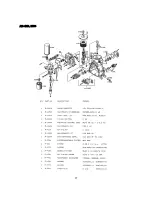
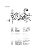
Page 31: ...27 AIR END NK40 ...
Page 33: ...29 AIR END NK60 ...
Page 34: ...30 Appendix B 1 PART LIST FOR MODEL CHSA 7 5M 1 2 ...
Page 35: ...31 1 PART LIST FOR MODEL CHSA 7 5M 2 2 ...
Page 36: ...32 2 PART LIST FOR MODEL CHSA 10M 1 2 ...
Page 37: ...33 2 PART LIST FOR MODEL CHSA 10M 2 2 3 PART LIST FOR MODEL CHSA 15M 1 2 ...
Page 38: ...34 3 PART LIST FOR MODEL CHSA 15M 2 2 ...
Page 39: ...35 4 PART LIST FOR MODEL CHSA 20M 1 2 ...
Page 40: ...36 ...
Page 41: ...37 4 PART LIST FOR MODEL CHSA 20M 2 2 ...
Page 42: ...38 C Wiring Diagram for Model CHSA 7 5 10 15 20M ...
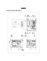
Page 43: ...39 Appendix D 1 Outline Drawing for Model CHSA 7 5 10M ...


