4
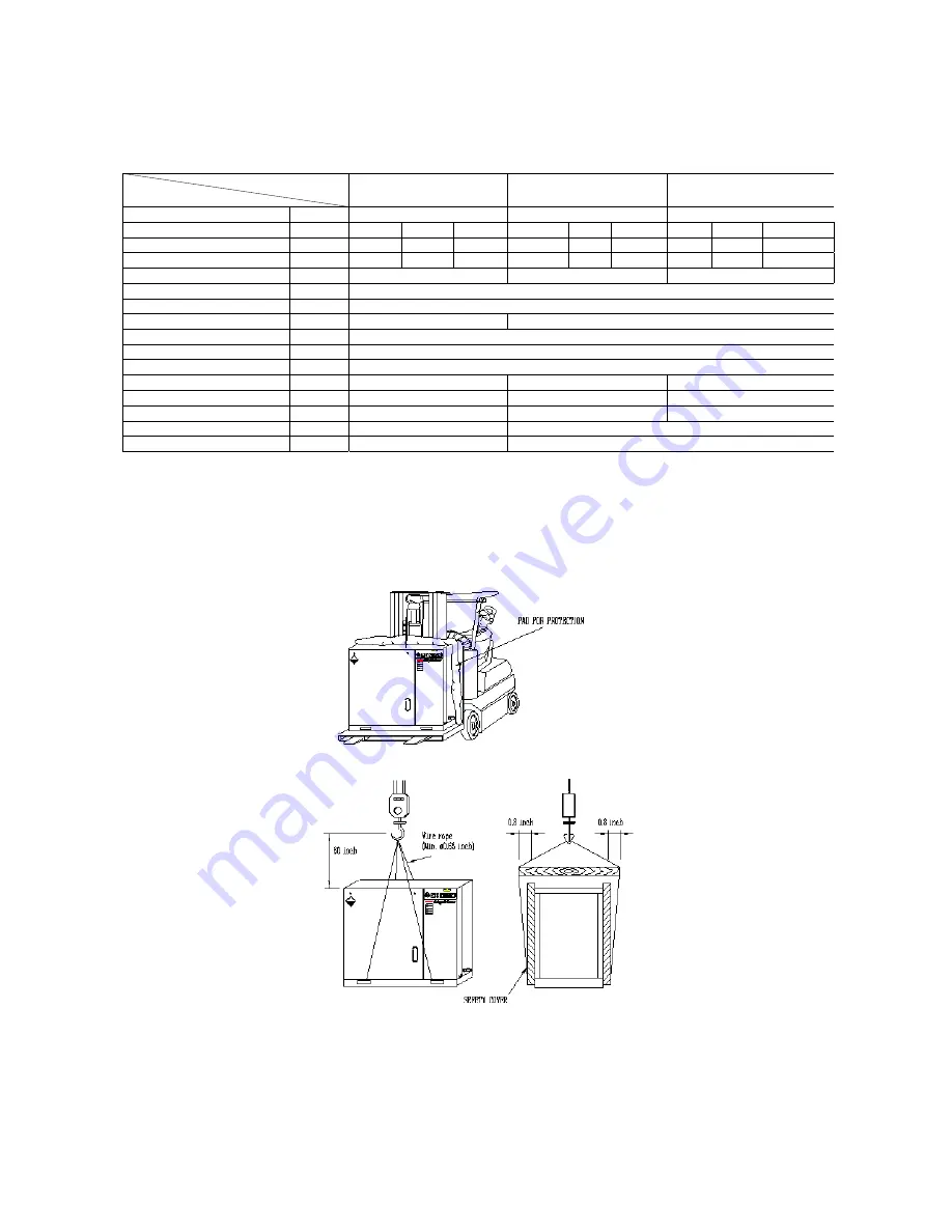
MODEL
ITEM
CHSA-20M
CHSA-25M
CHSA-30M
Motor output
Kw(HP)
15(20)
19(20)
22(30)
Discharge pressure
psi(g)
110
125
150
110
125
150
110
125
150
Air delivery cfm
73.4
68.0
64.0
125.3
115.0
108.0
Compressor speed
RPM
8280
7900
7500
5700
5380
5160
Oil flow rate
gpm
8.5
11.9
11.9
Ambient temperature
℉
32 115
∼
℉
Discharge air temperature
℉
Inlet air tempe 27 (MAX)
℉
Driving method
-
V-Belt
V-Belt
Voltage V
3Ph,
208-230/
460
Frequency Hz
60
Starting method
-
Direct on Start
Oil sump capacity
gal
1.1
1.3
1.3
Noise level
dB(A)
72
73
73
Weight lbs
450 550 630
Dimensions(W×D×H) in
28.3/4x41.3/8x42.1/8
31.1/2x47.1/4x49.7/8
Air outlet piping size
in
1”
1”
1-9. INSTALLATION AND WIRING.
Upon delivery, carefully check the air compressor unit(s) for damage during
transportation.
1-9-1. HANDLING.
When handling by a forklift, make sure that forks completely extend through the width of
the unit. When handling by a shop crane, use the openings provided on common base where slings or steel wire
ropes can be use for lifting.
Fig 1-6. Handling by forklift truck
Fig 1-7. Handling by shop crane
1-9-2. LOCATION.
The unit should be installed in a dry, well ventilated area dust-free environment. The unit
should not be installed outdoors. Consideration must be given to the need for clearance around the unit to avoid
the re-circulation of air-end for easy maintenance access.
Summary of Contents for CHSA-10M
Page 31: ...27 AIR END NK40 ...
Page 33: ...29 AIR END NK60 ...
Page 34: ...30 Appendix B 1 PART LIST FOR MODEL CHSA 7 5M 1 2 ...
Page 35: ...31 1 PART LIST FOR MODEL CHSA 7 5M 2 2 ...
Page 36: ...32 2 PART LIST FOR MODEL CHSA 10M 1 2 ...
Page 37: ...33 2 PART LIST FOR MODEL CHSA 10M 2 2 3 PART LIST FOR MODEL CHSA 15M 1 2 ...
Page 38: ...34 3 PART LIST FOR MODEL CHSA 15M 2 2 ...
Page 39: ...35 4 PART LIST FOR MODEL CHSA 20M 1 2 ...
Page 40: ...36 ...
Page 41: ...37 4 PART LIST FOR MODEL CHSA 20M 2 2 ...
Page 42: ...38 C Wiring Diagram for Model CHSA 7 5 10 15 20M ...
Page 43: ...39 Appendix D 1 Outline Drawing for Model CHSA 7 5 10M ...


