background image

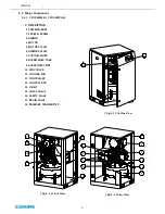
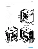
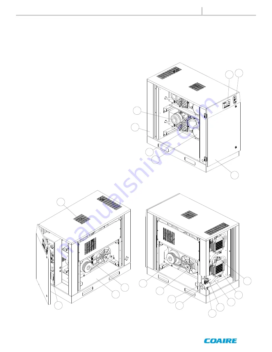
3-2-2  CSOF-S8PL(H), CSOF-S10PL(H) 

[ Fig.3-6 ] Rear View  

[ Fig.3-5 ] Right View 

#. DESCRIPTION 

 1. COMMON BASE 

 2. COVER & FRAME 

 3. AIREND 

 4. MOTOR 

 5. MOTOR PULLEY 

 6. AIREND PULLEY 

 7. SUCTION FILTER 

 8. AIR DELIVERY SOCKET 

 9. AIR DELIVERY PIPE 

10. AIR COOLER 

11. COOLING FAN 

12. CONTROLLER 

13. CONTROL BOX 

14. V-BELT 

15. CHECK VALVE 

16. SAFETY VALVE 

17. DRAIN VALVE 

18. PRESSURE TRANSMITTER 

GENERAL 

1

13

2

2

3

4

5

6

7

8

9

10

11

12

19

14

15

16

17

18

[ Fig.3-4 ] Left View  

Summary of Contents for SCROLL CSOF-M3PL/H12

Page 1: ...neral safety regulations and practices September 2012 OILLESS SCROLL AIR COMPRESSORS MAINTENANCE MANUAL AND PARTS LIST CSOF M3PL H12 CSOF M3PL H22 CSOF M3PL H32 CSOF M3PL H42 CSOF M5PL H22 CSOF M5PL H32 CSOF M5PL H42 CSOF S8PL H22 CSOF S8PL H32 CSOF S8PL H42 CSOF S10PL H22 CSOF S10PL H32 CSOF S10PL H42 All rights reserved Printed in U S A ...

Page 2: ...prior written authorization Said authorization may be obtained through our air compressor service department All air compressors parts materials must be returned freight prepaid to our factory within 30 days of return aut horization date Any shipment returned to the factory collect will be refused If an item is found to be warrantable the repaired item or replacement will be returned normal ground...

Page 3: ...ce 31 3 3 System diagram 8 9 0 Trouble Shooting 35 4 0 Installation 4 1 Inspection 10 10 0 Outline drawings 4 2 Handling 10 10 1 CSOF M3PL H CSOF M5PL H 39 4 3 Installation 11 10 2 CSOF S8PL H CSOF S10PL H 40 4 4 Requirements for the piping 12 4 5 Wiring 13 11 0 Electrical wiring drawings 11 1 CSOF M3PL H CSOF M5PL H 41 5 0 Operation 11 2 CSOF S8PL H CSOF S10PL H 42 5 1 Commissioning 16 5 2 Routin...

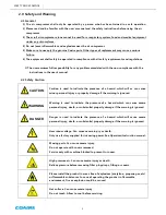
Page 4: ...th or substantial property damage if the warning is ignored Danger is used to indicate the presence of a hazard which will cause severe personal injury death or substantial property damage if the warning is ignored Hazardous voltage Can cause severe injury or death Only use factory supplied for incoming power See Operators Instruction manual Moving parts Can cause severe injury Do not operate with...

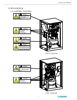
Page 5: ...T SURFACE HIGH PRESSURE SAFETY DEPRESSURE THE COMPRESSED AIR FLYING PARTS FROM COMPRESSED AIR CAN CAUSE INJURY OR DEATH COMPRESSED AIR FROM THIS MACHINE CONTAINS OIL MIST WHICH MAY CAUSE SEVERE NAUSEA INJURY OR DEATH NEVER USE AIR FROM THIS MACHINE TO SUPPLY BREATHING AIR AND KEEP UNIT IN A WELL VENTILATED AREA DO NOT TOUCH HOT SURFACE WILL CAUSE INJURY Fig 2 2 Rear Side Fig 2 1 Front Side ...

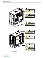
Page 6: ... COMPRESSED AIR CAN CAUSE INJURY OR DEATH COMPRESSED AIR FROM THIS MACHINE CONTAINS OIL MIST WHICH MAY CAUSE SEVERE NAUSEA INJURY OR DEATH NEVER USE AIR FROM THIS MACHINE TO SUPPLY BREATHING AIR AND KEEP UNIT IN A WELL VENTILATED AREA WILL CAUSE INJURY OR DEATH Fig 2 4 Rear Side Fig 2 3 Front Side 2 3 2 CSOF S8PL H CSOF S10PL H SAFETY AND WARINGS ...

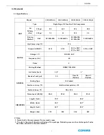
Page 7: ... 7 2 12 19 2 24 Driving Method Belt 3V 360x2EA 3V 380x2EA 3V 380x2EA 3V 405x2EA 3V 405x4EA High temp stop 176 MOTOR Output kW HP 2 2 3 3 7 5 2 2 3 x 1SET 3 7 5 x 1SET 3 7 5 x 2SET Voltage V 208 230 460 Frequency Hz 60 Poles 4 Starting Method DIRECT ON LINE GENERAL Air Outlet Inch 1 2 1 Receiver Tank gal 10 Over 16 Option Over 21 Option Cooling Type Air Cooled Service air temp Intake air temperatur...

Page 8: ...Y 6 AIREND PULLEY 7 SUCTION FILTER 8 AIR RECEIVER TANK 9 AIR DELIVERY PIPE 10 AIR COOLER 11 COOLING FAN 12 CONTROLLER 13 CONTROL BOX 14 V BELT 15 CHECK VALVE 16 SAFETY VALVE 17 DRAIN VALVE 18 PRESSURE TRANSMITTER GENERAL Fig 3 1 Outline View Fig 3 3 Rear View Fig 3 2 Front View 12 13 1 10 11 5 14 6 2 3 7 4 8 18 17 15 16 9 ...

Page 9: ...REND 4 MOTOR 5 MOTOR PULLEY 6 AIREND PULLEY 7 SUCTION FILTER 8 AIR DELIVERY SOCKET 9 AIR DELIVERY PIPE 10 AIR COOLER 11 COOLING FAN 12 CONTROLLER 13 CONTROL BOX 14 V BELT 15 CHECK VALVE 16 SAFETY VALVE 17 DRAIN VALVE 18 PRESSURE TRANSMITTER GENERAL 1 13 2 2 3 4 5 6 7 8 9 10 11 12 19 14 15 16 17 18 Fig 3 4 Left View ...

Page 10: ... into a water that can manually be discharged via a drain valve in the air tank There are following four safeguards in CSOF M3PL H and CSOF M5PL H models 1 Over Current Relay OCR for Motor Detects the over current of the motor to stop the compressor 2 Mechanical Safety Valve Mechanically discharges the compressed air in the air tank to the air if the air pressure exceeds the set value The compress...

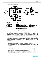
Page 11: ...to be used for example minimum capacity is 16gal for the CSOF S8PL H and 21gal for the CSOF S10PL H There are following four safeguards in CSOF S8PL H and CSOF S10PL H models 1 Over Current Relay OCR for Motor Detects the over current of each motor to stop only the motor failed 2 Mechanical Safety Valve Mechanically discharges the compressed air in the air tank to the air if the air pressure excee...

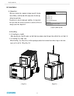
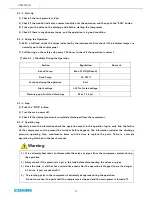
Page 12: ... that you notify the carrier and insist on a notation of loss or damage across the freight bill Fig 4 1 Name plate 4 2 Handling 4 2 1 Handling by a forklift When handling by a forklift make sure that forks completely extend through the width of the unit Fig 4 2 4 2 2 Handling by a shop crane When handling by a shop crane use the openings provided on common base where slings or steel wire ropes can...

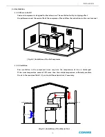
Page 13: ...in the room see Table 4 1 and install the exhaust duct if necessary Coaire air compressor is designed for the indoor use The ventilation facility and piping affect the performance and the service life of the compressor Please follow the instructions in the user s manual Fig 4 4 Installation of the Air Compressor INSTALLATION MIN 1000mm 39 4 MIN 1500mm 59 MIN 2000mm 78 8 Max V 3m s Max V 5m s EMERG...

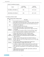
Page 14: ...ncrease of the inlet temperature reduces the efficiency of the compressor by 3 4 Hazardous Substances Install the compressor at the place where there is the least noxious gas hazardous substance and dust Those foreign substances may cause the damage of the air compressor Electricity The electric power shall have at least 150 of the reference margin The range of fluctuation in voltage shall be with...

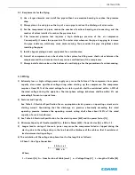
Page 15: ...he cable so that it maintains at least minimum starting voltage 6 The calculation of the voltage drop based on the line length is as follows 3 Phase 3 Line Type Connection Where I Current A A Cross Section of Cable mm2 e Voltage Drop V L Length of Cable M INSTALLATION 4 4 Requirements for the Piping 1 Use a larger diameter and install the pipe without an excessive bending to reduce the pressure dr...

Page 16: ...a motor or a control box to earth the equipment Type Ground Resistance Thickness of Grounding Conductor Application 1st Class Grounding 10Ω 2 6 mm2 or above High Voltage Equipment 2nd Class Grounding 150Ω 1 Line Ground Current or below 2 6 mm2 or above Neutral Point of Transformer 3rd Class Grounding 100Ω 1 6 mm2 or above Equipment with Low Voltage Less than 400 V Special 3rd Class Grounding 10Ω 1...

Page 17: ...63 8 30 15 10 15 2 5 460 4 2 32 3 30 10 5 15 2 5 CSOF M5PL H 4P 208 230 3 7 4 53 14 13 2 93 8 30 20 15 8 15 2 5 460 6 6 44 8 30 15 7 9 15 2 5 CSOF S8PL H 4P 208 230 2 2 3 7 2 84 4 53 8 4 14 13 2 63 8 93 8 50 40 10 15 8 11 4 460 4 3 6 6 32 3 44 8 30 20 5 7 9 15 2 5 CSOF S10PL H 4P 208 230 3 7 X 2EA 4 53 X 2EA 14 13 2 X 2EA 93 8 X 2EA 50 50 15 8 X 2EA 9 4 460 6 6 X 2EA 44 8 X 2EA 30 30 7 9 X 2EA 15 ...

Page 18: ... Commissioning 1 Push the START button on the controller to check the direction of rotation If it is operated in a negative phase immediately push the emergency stop button turn the main power off and then convert R into T before restarting When the compressor starts the pressure is increased in the airend to start the compression 2 With the discharge valve closed on the discharge side of the air ...

Page 19: ... 2 Routine Operation 5 2 1 Checklists before the Operation 1 Connect the main power to check the display on the monitor 2 Push the START button on the controller to check if the compressor is well started up and the indicator lamps are normally on 3 Check if there is any abnormal vibration noise and leakage 4 Check if the operation is in good condition at the maximum load Check the following condi...

Page 20: ... 2 Turn the main power off 3 Check if the internal pressure is completely discharged from the compressor 5 2 4 Stop Regularly record the information about the operation events in the operation log to early find the failure of the compressor and to prevent the accident before happens The information includes the discharge pressure operating time maintenance items and the time to replace the parts T...

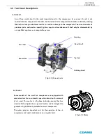
Page 21: ...ompressor The airend consists of precision parts and needs a special jig for a repair and maintenance It shall only be disassembled by our qualified engineer or a comparable person Some models of the scroll air compressor are equipped with several motors for an automatic operation based on the amount of air used The motor is a 3 phase induction motor that has a service factor higher than a general...

Page 22: ...ire suction filter A check valve plays an important role in the scroll air compressor The valve prevents the backflow of the compressed air when the compressor is stopped to protect the compressor from damaging due to a back lashing The valve also protects the wrap of the compressor from damaging due to foreign substances back flown from the pipe to the compressor The valve is designed to stand ag...

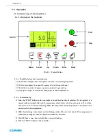
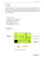
Page 23: ... a microprocessor for an optimal operation of the compressor The controller is a system that precisely determines the time to adjust the capacity to save the energy gives an alarm to prevent the accident before happens and notifies the information necessary for repair and maintenance The system ensures the best automatic operation optimized by the set conditions and the machine conditions 7 1 1 Op...

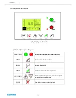
Page 24: ... condition MENU Enter to Menu table ENTER Confirm selection of value adjustment UP DOWN Scroll up down through menu menu item options or increment decrement value CANCEL Step back one menu navigation level 7 3 Configuration of functions Fig 7 2 Keypad of Controller Table 7 1 Description of Keypad ...

Page 25: ...ult or alarm status along ON OFF Machine state Number Machine state Status Green Fault Red 00 Initialization OFF Normal OFF Trip FF Alarm SF Maintenance IF Start Inhibit IF 01 Start Inhibit Check OFF 02 Ready to Start OFF 03 Start Delay IF if load request FF 04 Standby IF 06 Start Motor in star Delta IF if load request FF 07 Load Delay IF if load request FF 08 Load ON 09 Reload Delay IF if load re...

Page 26: ...play while compressor stopped LOC STP Stopped by controller keyboard REM STP Stopped by digital inputs NET STP Stopped by communication request Option S D STP Stopped by fault condition 4 START STATUS DISPLAY Display while compressor started LOC RUN Started by controller keyboard REM RUN Started by digital inputs NET RUN Started by communication request Option 5 COMPRESSOR STATUS DISPLAY GOOD Norm...

Page 27: ...in Motor 1 fault open DI2 Over load Main Motor 2 fault open DI4 Emergency Switch fault open DI5 Remote Start Stop Control Run closed DCM INPUT fault open Symbol Description Description N1 Compressor 1 Main Magnetic Contactor On N2 Compressor 2 Main Magnetic Contactor On NC1 N1 N2 N4 Run On N5 Alram On NC2 N4 N5 ...

Page 28: ...OPERATION SET 06 COMP SET 07 CONFIG MODE 00 STATUS MODE 01 PRESSURE MODE 02 SCHEDULE MODE 03 TRIP LOG MODE 04 TRIP SET 05 OPERATION SET 06 COMP SET 07 CONFIG MODE 08 FACTORY SET TIMEOUT PERIOD 1 MINUTE 10 MINUTE Press MENU button for a seconds in status mode an access code entry display Fig 7 4 is shown Use PLUS button to adjust value then press ENTER button If the access code have been entered to...

Page 29: ...EL button for three seconds at any time to return to the system locked condition ACCESS CODE 0100 Editable M E N U S T R U C T U R E 1 STATUS MODE 2 PRESSURE MODE TARGET PRESSURE STEP 1 STEP 2 START PRESS STEP 1 STEP 2 STOP PRESS LCD LIGHT MODE 3 SCHEDULE MODE 4 TRIP LOG MODE 5 TRIP SET 6 OPERATION SET 7 COMP SET 8 CONFIG MODE 7 3 9 Digital output ...

Page 30: ...MP LIMIT 9 8 Comp 2 Temp Detection Comp 2 Temp COMP TEMP LIMIT Reset Comp 2 Temp COMP TEMP LIMIT 9 An trip message is displayed that must be manually reset to clear once the condition has been resolved or no longer exists 7 4 2 Alarm condition Item Description Detect condition 1 RTC Real Time Clock Alarm Detection RTC Disable When Schedule Mode Operation Reset RTC Enable An trip message is display...

Page 31: ...V V Check Replace G Ventilation fan Check Motor pulley Check groove Motor Check insulation bearing G Suction hose Replace G After cooler Clean Clean case of abnormal Control panel Check monitor Piping Check leak Air end Overhaul G 8 1 Scheduled Maintenance Low pressure 115 psi Model CSOF M3 5PL CSOF S8 10PL Maintenance should be followed below criteria A B C Criteria A Under 2 500 working hours an...

Page 32: ...00hr G exchange in case of pollution Air end fan Clean Air end Bearing Clean G Air end grease Re grease Tip seal Replace G Dust seal Replace G Belt Check Replace first G Looseness makes noise Temp sensor Check operation Replace case of abnormal Pressure Sensor Check operation Replace case of abnormal Safety V V Check operation Check V V Check Replace G Ventilation fan Check Motor pulley Check groo...

Page 33: ...e for when the lubrication is needed The airend consists of precision parts and needs special tool and jig for a repair and maintenance It shall only be disassembled by our qualified engineer Contact the nearest distributor if necessary Caution 8 3 2 Rotation of the Driving Part If the motor is not started up or generates an abnormal noise stop the compressor turn the main power off and then manua...

Page 34: ... the tension with reference to the Table 8 1 3 Align the motor and tighten the anchor bolt on the motor base Off centered pulleys generate the noise and vibration and accelerate the process of wearing the belt and pulley to cause the damage to the belt Align the center of the pulley during the replacement of a belt and the adjustment of the belt tension With the compressor fixed loose the anchor b...

Page 35: ... the bearing is shorten at a high tension of the belt while the belt is slippery at a low tension of the belt Always keep the optimal tension value with reference to the Table 8 1 Caution 8 3 5 Cleaning the Suction Filter 1 Check the contamination level every 500 hrs 2 Replace the heavily contaminated filter even before the replacement period 3 Blow the element with the compressed air outward and ...

Page 36: ...case airend Back lash occurred This case may cause severe damage to airend because of foreign objects from outside To prevent possible defect check valve every 2 500hours 1 Screw CAP open 2 Check spring tension and SEAT of Check valve 3 Replace valve when it has been damaged Warning Be sure of 0 psi of air pressure It may cause injuries or severe damages MAINTENANCE ...

Page 37: ...d maintenance 9 2 Flow Diagram for Troubleshooting 9 2 1 No Display Negative phase operation Poor connection to power supply Convert the phase for two of three main power lines Abnormal noise Start Up Request a service No Display Poor connection to power supply Yes No Check the breaker switch Check the wiring Yes Failure of controller Check the fuse Check the transformer The controller is defectiv...

Page 38: ...check the bearing Replace the motor if necessary Yes No Failure of compressor No Manually turn to check the rotation Request a service if it is defective Failure of controller Check the output signal of the magnetic switch Turn the main power off and then on Yes Yes No Start Up Request a service No 1 An air compressor is automatically operated Take necessary safety precaution to ensure that the co...

Page 39: ... the magnet and the output of the controller Yes No Start Up Request a service No 9 2 5 Discharge Pressure Rise Discharge Pressure Rise Error message High pressure appears Check the operation of the pressure sensor No Yes Failure of controller Check the output of the controller No Failure of pressure sensor Safety valve is activated Pressure sensor or safety valve is defective Yes No Start Up Requ...

Page 40: ...le Cause Action 1 Tripped due to the over current in motor 1 Compressor is tripped Foreign substance in the compressor Damage to the wrap of the compressor Low voltage 2 Open phase Unbalanced power supply 3 Deteriorated coil in the motor 4 Failure of EOCR 1 Contact the distributor Improve the power supply 2 Improve the power supply 3 Check the motor 4 Readjust or replace 2 Noise and Vibration 1 Fi...

Page 41: ... DRAIN 1 4 AIR DISCHARGE 1 2 640mm 25 2 700mm 27 6 POWER IN CONTROLLER EXHAUST AIR OUTLET COOLING FAN EXHAUST AIR OUTLET SIROCCO FAN 166mm 6 5 118mm 4 6 57mm 2 2 28mm 1 1 213mm 8 4 25mm 1 150 5mm 5 9 260mm 10 2 100mm 3 9 740mm 29 1 1070mm 42 1 EMERGENCY STOP 301mm 11 9 153mm 6 ...

Page 42: ...AUST AIR OUTLET AIR OUTLET PS 25A PS1 1150mm 45 3 75mm 3 225mm 8 9 AIR INTLET 118mm 4 6 40mm 1 6 122mm 4 8 376mm 14 8 166mm 6 5 169mm 6 7 221mm 8 7 560mm 22 640mm 25 2 MAIN POWER INLET 160mm 6 3 1020mm 40 2 EMERGENCY STOP R S T Ground Main Terminal block ...

Page 43: ...ectrical wiring drawings 11 1 CSOF M3PL H CSOF M5PL H ELECTRICAL WIRING DRAWINGS 1 USE ONLY 230V or 460V POWER INPUT 2 WIRING COLOR B BLACK BL BLUE R RED Y YELLOW PRIMARY INPUT VOLTAGE SECONDARY 110V 100VA NOTES ...

Page 44: ...44 11 2 CSOF S8PL H CSOF S10PL H ELECTRICAL WIRING DRAWINGS 1 USE ONLY 230V or 460V POWER INPUT 2 WIRING COLOR B BLACK BL BLUE R RED Y YELLOW PRIMARY INPUT VOLTAGE SECONDARY 110V 100VA NOTES ...

Page 45: ...ed ______ Incoming Voltages L1 L2 L2 L3 L1 L3 Volts Volts Volts Full load amperage at _________ PSIG L1 L2 L3 Amp Amp Amp Unload amperage at _________ PSIG L1 L2 L3 Amp Amp Amp Is the machine on a level and stable surface Yes No Was a flexible connector used to connect piping Yes No Approx time spent during startup procedure ___________ Hrs Did you advice customer on operation and maintenance of m...

Page 46: ...t Temperature F No of days of operation weekly Days Discharge temperature F Hours per day Hours Compressor area temperature F Machine setting OL OL or Mod Environment 1 1 1 to 10 1 being clean 10 very dirty Incoming Voltages Full load amperage at _______ PSIG Unload amperage at ______ PSIG L1 L2 L2 L3 L1 L3 L1 L2 L2 L3 L1 L3 L1 L2 L2 L3 L1 L3 Volts Volts Volts Amp Amp Amp Amp Amp Amp Symptom Fault...

Page 47: ...QUALITY AND RELIABILITY WITHOUT COMPROMISE COAIRE reserves the right to make changes at any time without notice as a result of our commitment to continuous improvement ...

Reviews: