background image

Summary of Contents for Split-Type Room Air Conditioner

Page 1: ...er cord is damaged replacement work shall be performed by authorised personnel only It Installation work must be performed in accordance with the national wiring Standards by authorised personnel only_ It Contact an authorised service technician for repair maintenance or installation of this unit ...

Page 2: ......

Page 3: ...is a Inside you will illustrations are for V H tll n maybe Contact an Contact an The air conditioner is Young children If the power Installation work personnel air conditioner properly All the of the air conditioner you purchased I hlilr rc n or infirmed persons without supervision with the air conditioner no tru n Ic r by authorised personnel only wiring Standards by authorised ...

Page 4: ...nnection or fixing is not or fire at the connection 7 Wiring routing must be properly arranged so that control board cover is fixed nrnncrl l is not fixed perfectly it will cause heat up at connection of fire or olot trlt 1 8 When carrying out piping connection take care not to let air substances other than the refrigerant go into refrigeration cycle Otherwise it will cause lower capacity abnormal...

Page 5: ...nt Spanner ha Mora than 6 I More than sV 1 cabinet More than12 I More than12 More than 24 More than 2 or outlet a place where noise vibration conditioner disturb neighbors sure to level the un for the location excessive ...

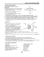
Page 6: ...he space around the left and of the indoor unit is more than indoor unit should a minimum of Use a stud finder to locate studs to prevent unnecessary to the wall A minimum run of 10 feet is to minimise excessive noise The indoor unit should be installed on the wall at of feet or more from the floor Two of the A Band C directions should be free obstructions Remote Controller Self tapping screw B ST...

Page 7: ...ing to the wall structure and corresponding mounting points on the installation plate Dimensions are in inch unless otherwise stated 43 mm or more to wall Left rear side refrigerant pipe hole i 6 or more to ceiling Indoor unit outline A Installation plate 31 I I 43 or more to wall Right rear side refrigerant 1 i e hole 2 2 A 12000Btu h model 31 12000Btu h 361 J B 12000Btu h model 107 J 12000Btu h ...

Page 8: ...ng as shown Bend the connective pipe to be laid at 1 3 J height or less from the wall 3 Fix the end of the connective pipe Refer to Tightening Connection in REFRIGERANT PIPING CONNECTION n II c Slid Part cover Left hand piping Rear left piping Fig 8 1 Pass the piping through the hole in the wall 2 Put the upper claw at the back of the indoor unit on the upper hook of the installation plate move th...

Page 9: ...oped downward to drain out the condensed water smoothly Outdoor unit installation Install the outdoor unit on a rigid base to prevent increasing noise level and vibration Determine the air outlet direction where the discharged air is not blocked In the case that the installation place is exposed to strong wind such as a seaside make sure the fan operating properly by putting the unit lengthwise al...

Page 10: ...A Air inlet 12 pipe Fig 13 9 ique R ness rr 14 L LII unit 15 ...

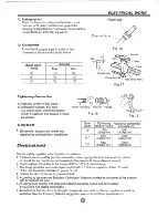
Page 11: ...kgf cm 1 J 4900 5390 500kgf cm 550kgf cm Electric safety regulations for the initial Installation 1 If there is serious safety problem about the power supply the technicians should refuse to install the air conditioner and explain to the client until the problem is solved 2 Power voltage should be in the range of 900 0 11 o0 0of rated voltage 3 The sorge protector and main power switch with a 1 5 ...

Page 12: ...espectively 5 Wrap those cables not connected with terminals any electrical components Secure the cable onto Panel Code wire Electrical cover 20 1 Remove the electrical control board cover from outdoor unit 2 Connect the connective cables to the terminals as identified with matched numbers on the terminal block of indoor and outdoor 3 Secure the cable onto the control board cord clamp 4 To prevent...

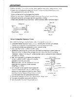
Page 13: ... the indoor unit and tubing between the indoor and outdoor unit must be leak tested and evacuated to remove any noncondensables and moisture from the system vacuum HUlmH Preparation Check that each be both liquid and side tubes between the indoor and outdoor u been com been properly and all wiring for the test run has Remove the service caps from both the gas and the liquid unit Note that both liq...

Page 14: ... 3 Fully open the handle Lo of the manifold valve 4 Operate the vacuum pump to evacuate After starting evacuation slightly loose the flare nut of the La valve on the gas pipe side and check that the air is entering Operation noise of the vacuum pump changes and a compound meter indicates oinstead of minus 5 After the evacuation is complete fully close the handle Lo of the manifold valve and stop t...

Page 15: ...t sh to of the connecting points th come out the pipes have 2 Leak detector Use the leak detector to check A La packed valve and D are indoor ra 1 Check that all tubing and wiring 2 Check that the gas and Jiquid completing more more 1 Hold the panel sides and push it upward remains fixed not lift the panel any further 2 Press the manual control button until will operate on Forced Cool mode 3 Check...

Page 16: ...Coaite Fort Worth TX 1 877 COAI 1 www coaire com 2020323A3919 ...

Reviews: