HANDBOOK (V
4.0)
COMPLETE CONTROL SYSTEM GEN2
17
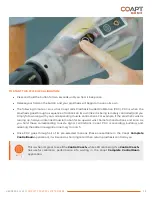
A HELPFUL APPROACH TO POSITIONING THE ELECTRODE CONTACTS:
•
Consider starting with locations that correspond to existing myosites when retrofitting
existing myoelectric users.
•
Identify locations to AVOID electrode contact, such as
o
Areas that will lose electrode-to-skin contact during use.
o
Areas outside of socket trim-lines or co-located with valves.
o
Areas that have no underlying muscle (i.e. bone only).
o
Sensitive skin areas.
o
Areas with active EMG during positional loading (e.g. deltoids, brachioradialis).
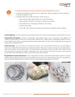
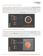
Contact Spacing
– Plan to place the two electrode contacts for an EMG channel approximately 30–60 mm apart.
Contact-Pair Orientation
– While it is generally a good idea to align a pair of contacts in the direction of
underlying muscle fiber direction, it is ok with pattern recognition to place some of the electrode pairs “off-axis”.
This is helpful when fitting a residual limb with unique areas of EMG interest, and for geometrically unique and
congenital limb presentations.
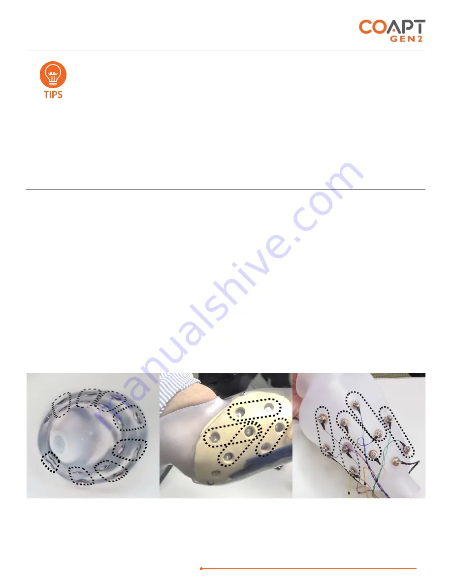
Contact Sharing
– For a limb that is too small to reliably fit all 17 Dome Electrode contacts, it is acceptable to
have a few of the EMG channels share an electrode contact. Take care, however, that you do not place the two
wires for any EMG channel (same color) on the same Dome Electrode—that will result in zero signal for that
channel and not be helpful for pattern recognition. Also very important: All Coapt Conductor wires must be
connected to a Dome Electrode contact; do not leave any unconnected.
Single Reference (Ground) Contact
– The Coapt system requires a single Dome Electrode contact for purposes
of EMG reference/ground. This contact should NOT be shared with any other EMG signal wires. The reference
contact should be positioned in a location that maintains excellent electrode-skin contact.
1
2
3
4
5
6
7
R
8
1
2
3
4
R
1
2
4
5
3
R


