background image

14

DEMOUNTING

Tubeless tires can be demounted in two ways:

1) 

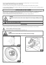
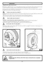
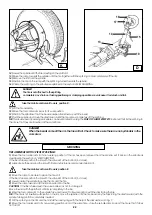
If the tire is not difficult to demount, once the beads have been loosened, use the bead disk to push against the inside face of the 

tire until both beads come off the rim (See Fig. H). Always keep the tire rotating while pushing on it with the bead disk.

2) 

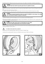
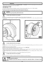
With Supersingle or very hard tires the procedure described above cannot be used. The hook tool will have to be used as follows:

- Transfer the tool carrier arm to the outside face of the tire.

- Insert lever 


 (17, Fig. I) between rim and bead at the right of the tool.

-Press down on the lever and lower the wheel to bring the edge of the rim about 2 inch (5 cm) from the hooked tool.

-Turn the wheel counterclockwise pressing down on lever 


 until the bead is completely off.

-Move the tool carrier arm to its non-working position and then move it to the inside face of the tire.

- Rotate the wheel and at the same time move the hook tool forward inserting it between rim and bead until it is anchored to the bead 

(See Fig. I).

-Move the rim 1,5-2 inch (4-5 cm) from the tool taking care that it does not unhook from the bead.

-Move the hook tool towards the outside until the red reference dot is by the outside edge of the rim.

-Place the tool carrier arm in the working position, then use the bead disck to push against the inside face of the tire (see fig. H). It is 

best to do this with the weel turning

Take the mobile control unit to work position C.

Take the mobile control unit to position B.

Take the mobile control unit to work position D.

  I

  H

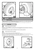
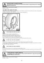
-Always keep the rotating counterclockwise, while pushing with the bead loosening disk

Turn the wheel counterclockwise pushing with disc


 until the tire comes completely off the rim.

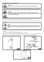
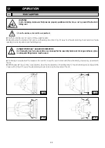
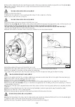
DANGER!

When the beads come off the rim, the tire will fall. Check to make sure there are no bystanders 

in the work area.

Take the mobile control unit to work position B.

Summary of Contents for CHD-6330

Page 1: ...sion 06 08 READ these instructions before placing unit in service KEEP these and other materials delivered with the unit in a binder near the machine for ease of reference by supervisors and operators...

Page 2: ...10 IDENTIFICATION OF CONTROL 9 11 WORKING POSITION 9 12 CORRECT OPERATION CHECKS 9 13 OPERATION 11 13 1 Rim clamping 11 Light alloy rim clamping 13 2 Tubeless and supersingle tires 12 Bead losening De...

Page 3: ...his machine is a violation of International Safety Regulations and as such once again relieves the manufacturer from all liability and warranty claims 4 SAFETY DEVICES The tire changer has a number of...

Page 4: ...f danger Keep the packing for possible future transport UNPACKING 7 INSTALLATION Choose the place the machine is to be installed in compliance with current work place safety regulations The floor shou...

Page 5: ...concrete slab as indicated in the drawing Tighten the anchor bolts completely Ground Reinforced concrete Electrowelded grid Pebble gravel When working with wheels whose weight is higher than 2 204 lb...

Page 6: ...n the data plate fixed to the tire changer Check to make sure the shop electric wiring circuit is dimensioned sufficiently to carry this Work on the electric system even if minor must be done exclusiv...

Page 7: ...tch 10 Pedal 13 Carriage 14 Tool holding arm 15 Arm lever 17 Bead losening disk 18 Tool 19 Pedal 22 Jaw WARNING During all operations keep hands and other parts of the body as far as possible from mov...

Page 8: ...the tire changer if one or more labels are missing Do not add any object that could prevent the operator from seeing the labels Use ref code 2019113 to order labels set if needed 3005419 3005423 3006...

Page 9: ...LOCKING and when moved down closes the arm of the self centering chuck UNLOCKING The pedal 10 fig C when pressed on the left or right side rotates the self centering chuck in the same direction as sh...

Page 10: ...e the lever down and the spindle arms should close 3 Depress the right pedal 10 Fig C the spindle 3 Fig A should turn clockwise depress the left pedal the spindle should turn counter clockwise DANGER...

Page 11: ...in vertical position oven the sliding ramp DANGER POTENTIALLY HAZARDOUS OPERATION Do it manually only if you are certain you can keep the tire assembly balanced For large and heavy tyres an adequate...

Page 12: ...lable upon request These clamps are to be inserted bayonet like mounting into the jaw support of the self centering chuck see fig E 7 Thanks to a wing screw the clamp can be locked on the support Clam...

Page 13: ...he arm to its non working position shift it and rehook it in its second work position Fig G DANGER Do not hold your hands on the tool when you bring it back to its work position Your hand s could be t...

Page 14: ...e it to the inside face of the tire Rotate the wheel and at the same time move the hook tool forward inserting it between rim and bead until it is anchored to the bead See Fig I Move the rim 1 5 2 inc...

Page 15: ...bead loosener disk against the second bead of the tire and turn the spindle until the g clamp is at the low point at 6 o clock 7 Move the disk away from the tire assembly 8 Remove the g clamp and repl...

Page 16: ...outside of the tire assembly and check the exact position of the hook visually and adjust it as needed Then turn the spindle clockwise until the g clamp is at the bottom 6 o clock The first bead will...

Page 17: ...it is anchored to the tool 3 Move the rim 1 5 2 inches 4 5 cm from the tool taking care that it does not unhook from the bead 4 Move the hook tool towards the outside until the red reference dot is b...

Page 18: ...MOUNTING 1 If the rim has been removed from the spindle put it back on the spindle as described in the section on RIM Clamping 2 Lubricate both beads and the rim with tire manufacturer recommended lu...

Page 19: ...and then remove the locking ring The purpose of this operation is to allow the valve to be loose so that it is not ripped out during second bead mounting 19 Lift the tire again and attach the g clamp...

Page 20: ...y and be prepared to stop the disk immediately once the bead has been loosened so as not to damage the valve and the inner tube 6 Repeat this procedure but this time bring the disk against the split r...

Page 21: ...g is released this ring can be removed with the special lever 19 Fig Z or with the help of the bead disk 6 Remove the O ring 7 Move the tool carrier arm 14 Fig D back from the edge of the rim Release...

Page 22: ...ool carrier arm to its non working position If the rim has been removed from the spindle put it back on the spindle as described in the section on RIM Clamping If the tire is tubed position the rim wi...

Page 23: ...with the lock ring already mounted If the rim and the split ring have slits for fixing devices make sure they are lined up with each other 7 Move the tool carrier arm to the outside in its work positi...

Page 24: ...hydraulic power pack Use the dipstick under the reservoir cap If necessary top up with Esso Nuto H46 or similar hydraulic oil eg Agip Oso 46 Shell Tellus Oil 46 Mobil DTE 25 Castrol Hyspin AWS 46 Che...

Page 25: ...Follow these instructions 1 Lower the clampingchuck arm 2 Fig A completely down 2 Close completely the jaws of the chuck 3 Fig A 3 Bring the sliding ramp 4 Fig A at the end of its travel near the arm...

Page 26: ...4 Phases 5 Voltage requirements 6 Frequency 7 Rated draw 8 Year 9 Weight 10 Absorbed power 19 DATA ON SERIAL PLATE These units are considered as special waste material and should be broken down into...

Page 27: ...27 The following optional accessories are available for the tire changer 20 ACCESSORIES...

Page 28: ...HENNESSY Industries INC 1601 J P Hennessy Drive LaVergne TN 37086 3565 USA Toll Free 800 688 6496 www ammcoats com...

Reviews: