background image

14 •

Important: Always read and follow the on-screen operating instructions.

V

Viid

de

eo

o  B

Ba

alla

an

nc

ce

er

r

A

Ad

dv

va

an

nc

ce

ed

d  B

Ba

alla

an

nc

ciin

ng

g

F

Fu

un

nc

ct

tiio

on

ns

s

This wheel balancer enables you to balance a variety

of wheel configurations. Read through this section, it
will help you determine which mode and options are
best suited for certain wheel assemblies.

Remember:

As with any balancing procedure, first

remove any weights attached to the wheel, inspect the
tire and wheel, and use the most appropriate balancer
mounting method before beginning.

Initial Screen Options

At the initial screen (see page 3), press the numbered

key that corresponds with the key icon along the bot-
tom of the video display screen for the following
options.

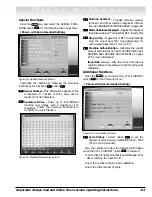
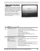
Mode -

select from several balancing types and

weight placement locations.

Figure 23 - Modes Screen

Dynamic -

the “initial screen” is a dynamic bal-

ance mode using two clip-on weight locations.

Note:

To reset the mode back to the initial screen at

any time, press the DYNAMIC option 

, or turn the

machine OFF then ON. Note that if an operator is in a
balance mode, it may be necessary to finish the bal-
ance cycle first.

DIM -

(available in 3D view) select to enter dimen-

sions manually. See MANUALLY SETTING
WHEEL DIMENSIONS on page 19 for further
details.

Roundoff -

toggle between 0.25-ounce or 0.01-

ounce weight increments.

Oper -

(available in 3D view) used to cycle

through (recall) an operator’s memorized meas-
urements. This wheel balancer can be used simul-
taneously by four operators. See SPECIAL
FUNCTIONS on page 13 for further details.

OZ/g -

(available in PROFILE view) toggle

between ounce or gram weight measurements.

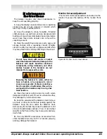
Profile

or 

3D -

Toggle between a profile or 3D tire

image for weight placement.

Figure 24 - The Profile and 3D Icons

7

5

5

4

3

2

2

1

Profile

3D

Summary of Contents for XR 1750

Page 1: ...red with the unit in a binder near the machine for ease of reference by supervisors and operators S Se ee e B Ba al la an nc ci in ng g Y Yo ou ur r F Fi ir rs st t T Ti ir re e o on n p pa ag ge e 2...

Page 2: ...necessary a cord with a cur rent rating equal to or more than that of the equip ment should be used Cords rated for less current than the equipment may overheat Care should be taken to arrange the cor...

Page 3: ...perating practices Always wear durable work clothing during tire service activity Loose fitting clothing should be avoided Tight fitting leather gloves are recommended to protect operator s hands when...

Page 4: ...to serious personal injury or death to operator or bystander or damage to property Do not operate this machine until you read and understand all the dangers warnings and cautions in this man ual For...

Page 5: ...cy conditions A hood guard of high impact plastic that is designed to prevent the counterweights from flying out in any direction except towards the floor A hood switch interlock system that prevents...

Page 6: ...NOTICE Read entire manual before assembling installing operating or servicing this equipment vi Important Always read and follow the on screen operating instructions S Sa af fe et ty y...

Page 7: ...s 14 Dynamic Modes 15 Static Modes 15 Special Modes 16 Additional Options 17 M Ma at tc ch hi in ng g 1 18 8 Optimization Match Balance 18 M Ma an nu ua al ll ly y S Se et tt ti in ng g W Wh he ee el...

Page 8: ...amount appears on the video display screen for the left and the right planes of the wheel see figure 3 7 Raise hood after tire stops rotating Note If the hood is raised before the end of the spin an e...

Page 9: ...an operator is in a balance mode it may be neces sary to finish the balance cycle first MENU 2 Figure 3 Weight Placement Screen Using Clip on Weights in Dynamic Mode Important Always read and follow t...

Page 10: ...s V Vi id de eo o B Ba al la an nc ce er r Monitor Sensor Target Bracket for calibration 40 MM Shaft Clip on Air Chuck for Tire Inflation Adjustment If equipped ON OFF and Circuit Breaker back of mach...

Page 11: ...cessory Storage Captured Cone Spring If equipped Positioning Pedal Holds Position for Weight Application Tilting Monitor Adjustment Knobs Adjustable Air Gauge Manual Tire Bleed Valve Inflate Button We...

Page 12: ...jury As shown the wheel balancer is equipped with the capability to adjust the air pressure of the tire The INFLATE push button supplies air through the hose and clip on air chuck located at the wheel...

Page 13: ...rm Viewed on a Cut Away Rim for Clarification To measure for a hidden weight location place the offset arm at a hidden weight placement location as shown in figure 10 Figure 10 Hidden Weight Location...

Page 14: ...d stops a measurement cycle or exits a screen as noted in instructions 2 To select a screen option press the numbered key that corresponds with the key icon along the bottom of each video display scre...

Page 15: ...lay Mode Icon Static Unbalance Icon appears when over 1 1 oz is present Profile Tire Image On selected screens can toggle to a 3D tire image Numbered Key Key Icons Monitor and Initial Screen Feature R...

Page 16: ...p Language English Screensave time 0 min Clock setting Video sleep mode time 60 min 4 3 2 1 Clock Setting Month 7 Day 24 Year 2004 Hour 15 Minutes 5 Day THU 12 24 Hour Clock 24 7 6 5 4 3 2 1 Balancing...

Page 17: ...On screen Instructions Tire Rim Weight Optimization On screen Instructions Alphabet Entry On screen Instructions Alphabet Entry On screen Instructions Self Test Screen Diameter Arm Calibration On scre...

Page 18: ...ncing Set up Screen Display Units Toggle to set OZ ounce or G gram weight measurements Lower Weight Limit Set the limit within the fol lowing tolerances 0 13 0 50 oz ounces 0 01 increments 4 10 g gram...

Page 19: ...play of the Static on Screen value ON or OFF Set to ON Stop On Top Toggle ON or OFF to automatically stop the wheel near TDC top dead center for outer weight placement Set to OFF Machine Self calibrat...

Page 20: ...types and weight placement locations Figure 23 Modes Screen Dynamic the initial screen is a dynamic bal ance mode using two clip on weight locations Note To reset the mode back to the initial screen...

Page 21: ...ocations ALU 1 ALU 2 ALU 3 ALU 4 Have the following items handy an appropriate wheel assembly mounted on the balancer and Tape A Weights You must use the appropriate measure ment and weight placement...

Page 22: ...inflation of a tire Training is necessary in tire changer opera tion and understanding the dangers involved during bead seating and tire infla tion before attempting this stage of the Patch Weight Bal...

Page 23: ...E option 4 Rotate the wheel to position the right side yellow marker ball until it turns green Select NEXT option 5 Rotate tire toward you until the first spoke is at 12 o clock or TDC Hold location a...

Page 24: ...ive it may be prudent to replace the rim the tire or both If either is replaced do not continue with optimization Balance the new tire and rim and evaluate the readings If you choose to use Optimizati...

Page 25: ...tting DIM option Manually Setting A DIM 1 Press SELECT option to highlight in red the rim offset A DIM 2 Position offset arm at clip on weight location on wheel and read the number on the slide out of...

Page 26: ...e balance Regardless of mounting type always make sure that the wheel is forced firmly against the shaft faceplate and that the hub nut engages the threaded shaft for at least four complete turns To a...

Page 27: ...re 34 Front Cone Mounting Alternate Mounting If the wheel has a protruding outer hub which will not permit the use of the pressure cup or the cup will not permit the hub nut to engage at least four tu...

Page 28: ...ctional Check Per Procedure Check for Proper Phase at Machine Self Test Screen To check for these causes press EXIT or press NEXT to continue 2 Mount a 14 15 or 16 steel wheel with tire A balanced tir...

Page 29: ...Recommended setting is 70 F Note Calibrate the offset arm first since it is very important that the wheel dimensions are correct Distance Arm Calibration Follow these instructions on screen when cali...

Page 30: ...osition 7 Calibration accepted Note The sonar calibration target bracket is stored flush with the side of cabinet at all other times see fig ure 42 Figure 42 Sonar Target Bracket in Stored Position Di...

Page 31: ...heck hood switch operation 4 Replace the encoder unit 5 Motor disconnected or bad wiring check for motor voltage at power PCB check circuit breaker check machine power 6 If motor hums remove belt and...

Page 32: ...ck the wheel dimensions setting 2 Check the piezo pick ups connections electrical mechanical in MACHINE SELF TEST Green Screen push on spindle shaft and verify that both piezo outputs change 3 Execute...

Page 33: ...peration clearance 020 to 035 3 Check motor operation 4 Check belt tightness 5 Check hub nut tightness 6 Replace the main PCB 1 Press and respin Check PHASE VCO dynamic VCI static in MACHINE SELF TEST...

Page 34: ...ance If a wheel is out of balance the cause maybe Wheel was not mounted centered correctly on the balancer A weight has come off the wheel possibly the wrong clip style Remove the other weights from t...

Page 35: ...Sensitive electronic components wiring harnesses and other devices housed in the balancer are not intended to be exposed to water Exposing the balancer to water either by hose or bucket or by exposure...

Page 36: ...der wheel balancers may require dif ferent voltages See serial tag for the appropriate power requirements of your machine Setup Do not use the monitor monitor base accessory storage faceplate hood or...

Page 37: ...Adjustments Automatic Data Entry for Offset Diameter and Width if equipped Manual Entry Backup on all Parameters Interactive Screens for all Modes and Functions with Superior Graphic Displays Static...

Page 38: ...duated Cone Assortment Small Cone 8112098 Medium Cone 8112099 Large Cone 8112100 40 MM ID Hardened and Ground both ID and OD Large Adapter Truck Cone 8112101 Cone Spring Permanently Retained in Facepl...

Page 39: ...and 0 006 normally Inner Plane the closest corrective weight location from the balancer Lug Centric refers to mounting and means the wheel is centered by the studs and nuts mounted on the axle of the...

Page 40: ...8113764 04 11 05 Copyright 2003 Hennessy Industries and COATS All Rights Reserved Printed in USA...

Reviews: